

Perkins 1204E-E44TA 1204E-E44TTA 1206E-E66TA 1206E-E70TTA Electriacal & Electronic A&I Guide
TABLE OF CONTENTS:
Perkins 1204E-E44TA 1204E-E44TTA 1206E-E66TA 1206E-E70TTA Electriacal & Electronic A&I Guide
10 INTRODUCTION AND PURPOSE 9
11 APPLICABLE ENGINES 9
12 ELECTRONIC APPLICATIONS CONTACTS9
13 SAFETY 9
131 Warning – Welding10
132 Warning – Electrostatic Paint Spraying10
133 Warning – Jump Starting10
20 ENGINE & AFTERTREATMENT COMPONENT OVERVIEW11
21 MAIN ENGINE SENSOR AND ACTUATOR DETAILS 11
211 Electronic Control Module (ECM)12
212 Fuel System12
213 Engine Speed 12
214 Core Engine System13
215 NRS (Nox Reduction System)13
216 Air System14
217 Emissions System Assist Devices 14
22 AFTERTREATMENT SYSTEM SENSOR & ACTUATOR DETAILS15
221 ARD (Auxiliary Regeneration Device) System 15
222 DPF System 16
23 SYSTEM COMPONENT DIAGRAMS AND SCHEMATICS17
231 1204E-E44TA Factory Installed Wiring and Components 17
232 1204E-E44TA Customer Installed Aftertreatment Wiring & Components18
233 1206E-E66TA Factory Installed Wiring and Components 19
234 1206E-E66TA Customer Installed Aftertreatment Wiring & Components20
235 1206E-E70TTA Factory Installed Wiring and Components21
236 1206E-E70TTA Customer Installed Aftertreatment Wiring & Components22
24 ENGINE & AFTERTREATMENT COMPONENT LAYOUT DIAGRAMS 23
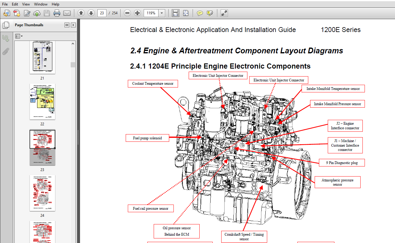
241 1204E Principle Engine Electronic Components 23
242 1206E Principle Engine Electronic Components 24
243 1206E-E70TTA Principle Engine And Aftertreatment25
244 1206E-E70TTA CEM Principle Electronic Components26
30 CUSTOMER SYSTEM OVERVIEW KEY ELEMENTS27
31 AFTERTREATMENT CONNECTIONS 27
32 CONNECTION, POWER AND GROUNDING27
33 INDICATION, STARTING AND STOPPING THE ENGINE27
34 CONTROLLING THE ENGINE28
35 AFTERTREATMENT OPERATION AND REGENERATION 28
38 OPTIONAL CUSTOMER INSTALLED COMPONENTS 30
39 TYPICAL CUSTOMER INSTALLED COMPONENT DIAGRAM 31
391 Example OEM Schematic 31
392 Example 1 Basic Engine Application31
393 Example 2 Construction Application31
394 Example 3 Agricultural Application31
395 Example 1 – Basic Schematic OEM Harness32
396 Example 2 – Construction Schematic OEM Harness33
397 Example 3 – Agricultural Schematic OEM Harness 34
40 POWER AND GROUNDING CONSIDERATIONS35
41 ENGINE BLOCK GROUNDING35
411 Ground stud on Starter Motor 35
412 Ground Connection to Tapping on engine Block 35
413 CEM Grounding 1206E-E70TTA 37
42 VOLTAGE AND CURRENT REQUIREMENTS 38
43 ECM POWER SUPPLY CIRCUIT RESISTANCE 39
431 Important Voltage Supply Circuit Considerations 41
Electrical & Electronic Application And Installation Guide 1200E Series
Draft Release Version P1, Publication TPD1725E1 Page 3 of 254
Created On 11/10/2011 13:26
432 Battery (+) Connection41
433 Battery (-) Connection 43
434 Correct method of ECM battery connection44
435 Incorrect method of ECM battery connection 44
44 ENGINE ECM POWER SUPPLY CIRCUIT RESISTANCE TEST 45
441 Test Procedure46
442 Suppression of Voltage Transients 46
45 DIRECT BATTERY CONNECTION REQUIREMENTS 48
46 POWERING THE ENGINE ECM VIA AUXILIARY POWER SUPPLIES48
47 SENSOR COMMON CONNECTIONS48
471 Actuator Driver Return49
472 Analogue Sensor Return 49
473 Switch Return49
474 Digital Return50
48 MANDATORY FUEL LIFT PUMP INSTALLATION 50
481 Fuel Lift Pump Operation50
482 Fuel Lift Pump Configuration 50
483 Fuel Lift Pump Installation51
50 CONNECTORS AND WIRING HARNESS REQUIREMENTS53
51 ENGINE ECM J1 CONNECTOR 53
511 Connector Layout 54
512 Tightening the OEM Connector54
513 ECM connector Wire Gauge Size 54
514 Terminal Retention 55
515 Hand Crimping For Prototype machines and Low Volume Production: 55
516 ECM connector sealing plug installation guidelines55
517 OEM harness Dress Cover With Integrated Strain Relief 55
518 Machine Crimping For High Volume Production 56
52 ENGINE TO AFTERTREATMENT CONNECTORS 1206E-E70TTA ONLY 57
521 40 Way CEM Connector Layout 1206E-E70TTA57
522 Engine Harness 31 pin Connector Layout 1206E-E70TTA58
523 Tightening the Connectors58
524 Aftertreatment Connectors Wire Gauge Size58
525 Connector Sealing Plug Installation Guidelines 59
526 OEM Harness Retention59
527 Harness Routing and Length Restrictions 59
53 DIAGNOSTIC CONNECTOR 60
531 Diagnostic Connector Layout60
532 Diagnostic Connector Wire Gauge Size 61
533 Pin Information 61
54 CONNECTOR TERMINAL CONTACTS 62
55 HARNESS WIRING STANDARDS 63
541 Connectors63
542 Harness Bends Near Connectors63
543 Cable routing64
545 Electromagnetic Compliance (EMC)65
546 Insulation Selection and Thermal Protection 65
60 CONNECTING TO ENGINE AFTERTREATMENT 66
61 1204E AND 1206E EMISSION CRITICAL AFTERTREATMENT INSTALLATION 67
611 Low Temperature Regeneration System Overview 67
612 Low Temperature Regeneration 68
613 System Connection and Harness Design 69
614 Aftertreatment Wiring Schematic 70
62 1206E-E70TTA EMISSION CRITICAL AFTERTREATMENT 71
621 High Temperature Regenerations System Overview 71
622 High Temperature ARD Regeneration 72
623 1206E-E70TTA High Temperature Regeneration System Connection and Harness Design73
624 Aftertreatment Wiring Schematic 77
Electrical & Electronic Application And Installation Guide 1200E Series
Draft Release Version P1, Publication TPD1725E1 Page 4 of 254
Created On 11/10/2011 13:26
64 AUXILIARY SENSOR INSTALLATION AND CONNECTION 78
641 DPF Soot Sensor 78
642 Air Inlet Temperature Sensor 82
643 DPF Inlet Temperature Sensor84
644 DPF Identification Module86
645 ARD Fuel Pump87
70 STARTING AND STOPPING THE ENGINE 92
71 STARTING THE ENGINE92
72 STOPPING THE ENGINE (AND PREVENTING RESTART) 93
721 Ignition Keyswitch 93
722 Battery Isolation Switches 94
723 User Defined Shutdown Switch (Remote Shutdown) 94
724 Intake Air Shutoff Valve95
725 Overspeed Verify Switch96
726 Datalink stops96
727 Common problems with the application of stop devices97
80 MACHINE FAN CONTROL 98
81 HYDRAULIC FAN CONTROL OPERATION 98
811 Machine Fan Control Operation 98
812 Machine Fan Control Configuration98
813 Machine Fan Control Installation 99
90 ENGINE SPEED DEMAND 101
91 ANALOGUE SENSOR 102
911 Analogue Sensor Operation102
912 Analogue Sensor Configuration 102
913 Analogue Sensor Installation103
914 Evaluating Component Compatibility (Testing) 103
92 PWM SENSOR – COMPATIBILITY106
921 PWM Sensor Operation106
922 PWM Sensor Configuration107
923 PWM Sensor Installation107
93 THROTTLE LOCK (PTO MODE)108
931 Throttle Lock Mode Operation 108
932 Throttle Lock Mode Configuration112
932 Throttle Lock Mode Installation 112
933 Throttle Lock Operation Under Engine Load113
94 MULTI POSITION THROTTLE SWITCH (MPTS)114
941 MPTS Operation114
942 MPTS Configuration115
943 MPTS Installation115
95 TORQUE SPEED CONTROL TSC1 (SPEED CONTROL OVER CAN)116
96 ARBITRATION OF SPEED DEMAND116
961 Manual Throttle Selection Switch116
97 ACCELERATION AND DECELERATION RAMP RATES 116
98 THROTTLE BEHAVIOR DURING ENGINE GOVERNOR CHANGES 117
991 Throttle Parameter Description 120
992 Throttle Calibration Function 122
993 Idle Validation Switch 126
910 DEFINITION OF ENGINE SPEED POINTS 127
9101 Engine Low Idle128
9102 Engine High Idle128
9103 Engine Rated Speed129
100 COLD WEATHER ENGINE OPERATION & STARTING AIDS 130
101 CONTROL OF GLOW PLUGS BY THE ENGINE ECM132
1011 Glow Plug System Operation132
Electrical & Electronic Application And Installation Guide 1200E Series
Draft Release Version P1, Publication TPD1725E1 Page 5 of 254
Created On 11/10/2011 13:26
1012 Glow Plug System Configuration 134
1013 Glow Plug System Installation134
102 ETHER COLD START SYSTEMS 136
1021 Ether start Operation136
1022 Ether start Configuration 136
1023 Ether start Installation136
103 COLD WEATHER REGENERATION AID138
1031 Cold Weather Regeneration Aid Operation138
1032 Cold Weather Regeneration Aid Configuration 138
1033 Cold Weather Regeneration Aid Installation138
104 HEATED BREATHER139
1041 Heated Breather Operation 139
1042 Heated Breather Configuration139
1043 Heated Breather Installation 140
110 ENGINE & AFTERTREATMENT MONITORING – HIGH LEVEL
INDICATORS & OPERATOR DISPLAYS141
111 ENGINE MANAGEMENT SYSTEM STATUS INDICATION 141
1111 Engine Monitoring System Fault Status Levels 141
1112 Hardwired Lamp Monitoring System Display 142
1113 Data Link Driven J1939 Monitoring System Display142
112 GAUGE DRIVERS 143
1121 Datalink Driven Intelligent Displays144
1122 Minimum Functional Specification for J1939 display144
1123 Customer Triggered Engine Fault codes144
113 LAMP OUTPUTS146
1131 ISO Reference For Aftertreatment Symbols146
1132 Indicator lamps Logic147
1133 Engine Shutdown Lamp 150
1134 Engine Warning Lamp150
1135 Wait to Start Lamp151
1136 Low Oil Pressure Lamp151
1137 DPF Lamp 152
1138 HEST (High Exhaust System Temperature) Lamp152
1139 DPF Regeneration Disable lamp153
114 ACTIVATION OF J1939 INDICATORS 154
120 ENGINE AND AFTERTREATMENT MONITORING SYSTEM 155
121 GENERAL INFORMATION 155
1211 Engine Monitoring Level 155
1212 Parameter Severity Levels 156
1213 Monitoring System Example157
122 ENGINE MONITORING & PROTECTION158
1221 Coolant Temperature158
1222 Engine Oil Pressure159
1223 Intake Manifold Temperature 160
1224 Engine Overspeed161
123 AFTERTREATMENT MONITORING & PROTECTION162
130 MONITORED INPUTS FOR CUSTOMER FITTED SENSORS163
131 AIR FILTER SERVICE INDICATOR – AIR INTAKE RESTRICTION SWITCH164
1311 Air Intake Restriction Switch Operation164
1312 Air Intake Restriction Switch Configuration164
1313 Air Intake Restriction Switch Installation165
132 COOLANT LEVEL SWITCH 165
1321 Coolant Level Switch Operation165
1322 Coolant Level Switch Configuration166
1323 Coolant Level Switch Installation167
133 WATER IN FUEL TRAP SWITCH 167
Electrical & Electronic Application And Installation Guide 1200E Series
Draft Release Version P1, Publication TPD1725E1 Page 6 of 254
Created On 11/10/2011 13:26
1331 Water In Fuel Trap Switch Operation 167
1332 Water In Fuel Trap Switch Configuration168
1333 Water In Fuel Trap Switch Installation 168
134 AUXILIARY TEMPERATURE SENSOR169
1341 Auxiliary Temperature Sensor Operation169
1342 Auxiliary Temperature Sensor Configuration 169
1343 Auxiliary temperature Sensor Installation170
135 AUXILIARY PRESSURE SENSOR 171
1351 Auxiliary Pressure Sensor Operation171
1352 Auxiliary Pressure Sensor Configuration172
1353 Auxiliary pressure Sensor Installation 172
140 REGENERATION SYSTEM & CUSTOMER INTERFACE173
141 LOW TEMPERATURE REGENERATION SYSTEM OPERATION173
1411 Low Temperature Regeneration System Overview 174
142 LOW TEMPERATURE REGENERATION OPERATOR INTERFACE 174
1421 Low Temp Regeneration Lamp Strategy174
143 LOW TEMPERATURE REGENERATION SYSTEM OPERATION EXAMPLE175
144 HIGH TEMPERATURE DPF REGENERATION SYSTEM OPERATION176
1441 High Temperature Regeneration System Overview176
1442 High Temperature Regeneration System Integration 177
1443 High Temperature Regeneration Decision Tree177
1444 Low Speed Regeneration (LSR) 181
1445 High Speed Regeneration (HSR) 184
1446 HSR and LSR Interaction186
1447 Regeneration Force/Inhibit Interface Switch187
145 TOTAL REGENERATION SYSTEM OPERATION EXAMPLE190
146 HIGH TEMPERATURE REGENERATION SYSTEM OPERATOR DISPLAY193
1461 Lamp Strategy193
1462 Integrated Machine Solutions Over J1939 194
147 INITIAL INSTALLATION REQUIREMENTS 195
1471 1204 – 1206E <130kw195
1472 1206E > 130kw195
150 ENGINE GOVERNOR 196
151 MIN/MAX GOVERNING196
1511 Operation196
1512 Configuration 197
1513 Installation197
152 ALL SPEED198
1521 Operation198
1522 Configuration 200
1523 Installation200
153 AUXILIARY GOVERNOR200
154 RATING SELECTION VIA SERVICE TOOL200
155 ENGINE HIGH SPEED GOVERNOR (GOVERNOR RUN-OUT)201
1551 Engine High Speed Governor Operation201
1552 Engine High Speed Governor Configuration 201
156 MODE SELECTION 201
1561 Operation201
1562 Configuration 202
1563 Installation202
1564 Rating and Droop changes requested via the J1939 datalink 203
160 TIER 4 INTERIM SERVICE TOOL FEATURES 204
161 INTRODUCTION204
162 SERVICE TOOL FEATURES FOR A 1206E-E70TTA 204
163 SERVICE TOOL FEATURES FOR A 1204E &1206E 204
170 DATALINK SUPPORT 205
Electrical & Electronic Application And Installation Guide 1200E Series
Draft Release Version P1, Publication TPD1725E1 Page 7 of 254
Created On 11/10/2011 13:26
171 SAE J1939205
1711 Summary of Key J1939 Application Issues205
1712 Physical layer 205
1713 Network Layer 206
1714 Application Layer 206
172 CONNECTION AND USE OF THE J1939 CAN BUS207
180 J1939 SUPPORTED PARAMETERS QUICK REFERENCE208
190 J1939 PARAMETERS – DETAILED DESCRIPTIONS 214
191 SENDING MESSAGES TO THE ENGINE ECM214
1911 Source Addressing 214
1912 Configurable ECM Source Addressing214
1913 Destination Addressing214
192 J1939 SECTION 71 – TSC1 OPERATION 215
1921 Torque Speed Control (TSC1) Operating Principles215
1921 Torque Speed Control (TSC1) Message Configuration & Control 217
193 J1939 ENGINE ECM TRANSMIT PGN SUPPORT219
1931 Electronic Brake Controller 1 (EBC1) (61441)219
1932 Electronic Engine Controller 2 (EEC2) (61443)219
1933 Electronic Engine Controller 1 (EEC1) (61444)220
1934 Turbocharger Wastegate (TCW) (65174)221
1935 Auxiliary Discrete IO state (AUXIO) (65241)222
1936 Software Identification (SOFT) (65242)223
1937 Engine Fluid Level / Pressure 2 (EFL/P2) (65243)224
1938 Electronic Engine Controller 3 (EEC3) (65247)224
1939 Engine Configuration (EC) (65251)225
19310 Shutdown (SHUTDOWN) (65252)226
19311 Engine Hours / Revolutions (HOURS) (65253)227
19312 Fuel Consumption (LFC) (65257) 227
19313 Engine Temperature (ET1) (65262) 228
19314 Engine Fluid Level / Pressure (EFL/P1) (65263)228
19315 PTO information (PTO) (65264) 229
19316 Fuel Economy (LFE) (65266)230
19317 Inlet / Exhaust Conditions (IC) (65270) 230
19318 Vehicle Electrical Power (VEP) (65271)231
19319 Operator Primary Intermediate Speed (ISCS) (64968) 231
19320 Off highway Engine control selection state (OHCSS) (64967)232
19321 Service Information (Maintenance Indicator Feature) (SERV) (65216) 233
19322 Aftertreatment 1 Historical Information (AT1HI) (64920)234
19323 Ambient Conditions (AMB) (65269)234
19324 Auxiliary Analogue (AAI) (65164)235
19325 Engine Speed Sensor Information (ESSI) (61473)235
19326 Aftertreatment 1 Service (AT1S) (64891) 236
19327 Diesel Particulate Filter Control 1 (DPFC1) (64892) 236
19328 Aftertreatment 1 Intake Gas 2 (AT1IG2) (64948)238
19329 Engine Temperature 3 (ET3) (65129) 238
19330 Engine Throttle/Fuel Actuator Control Command (TFAC) (61466) 239
194 J1939 ENGINE ECM RECEIVE PGN SUPPORT240
1941 Cab Message 1 (CM1) (57344) 240
1942 Off highway engine control selection (OHECS) (64971) 241
195 J1939 SECTION 73 – DIAGNOSTIC LAYER242
1951 Active Diagnostics Trouble Codes (DM1)242
1952 Previously Active Diagnostic Trouble Codes (DM2) 242
1953 Diagnostic Data Clear / Reset of Previously Active DTCs (DM3)243
196 SUPPORTED PARAMETERS – SECTION 21 – SIMPLIFIED DESCRIPTIONS244
1961 Transport Protocol – Connection Management (TPCM_BAM))244
1962 Transport Protocol – Data Transfer (TPDT) 244
1963 Proprietary A244
1964 Acknowledge244
Electrical & Electronic Application And Installation Guide 1200E Series
Draft Release Version P1, Publication TPD1725E1 Page 8 of 254
Created On 11/10/2011 13:26
1965 Request PGN 244
197 SUPPORTED PARAMETERS – SECTION 81 NETWORK MANAGEMENT – DETAILED DESCRIPTIONS
245
200 APPENDICES 246
201 APPENDIX 1 – ECM J1 CONNECTOR TERMINAL ASSIGNMENTS 246
202 APPENDIX 2 – ECM J2 TERMINAL ASSIGNMENT 248
203 APPENDIX 3 – ELECTRONIC OPTIONS SELECTION FORM250
204 APPENDIX 4 – LIST OF DIAGNOSTIC AND EVENT CODES251
205 APPENDIX 5 – DOCUMENT CHANGE TRACKER254
DESCRIPTION:
Perkins 1204E-E44TA 1204E-E44TTA 1206E-E66TA 1206E-E70TTA Electriacal & Electronic A&I Guide
1.0 Introduction and Purpose :
This document is intended to provide the information necessary for correct electrical and electronic installation of 1204E or 1206E Industrial engines, into an off-highway machine. Perkins expects that there will be some additions and modifications to this document as the engine program development continues, and as OEM requests for information not currently addressed are added. The Information herein is the property of Perkins and/or its subsidiaries. Without written permission, any copying, transmission to others and any use except that for which it is loaned is prohibited.
1.1 Applicable Engines
The information contained with this document is the best available at the time of authoring and describes the application and installation requirements for a production representative engine and software configuration. During development stages please ensure the Applications Engineering department are consulted before implementing any of the features contained within this document.
Early project engines will not have all the features described in this document enabled. Contact the Electronic Applications Team for latest information on software feature release dates.
1.2 Electronic Applications Contacts:
If the information in this document is incomplete, incorrect, or further details are required, then please contact your Applications Engineer.
1.3 Safety:
Most accidents that involve product operation, maintenance and repair are caused by failure to observe basic safety rules or precautions. An accident can often be avoided by recognizing potentially hazardous situations before an accident occurs.
VIDEO PREVIEW OF THE MANUAL:

IMAGES PREVIEW OF THE MANUAL:

PLEASE NOTE:
- This is not a physical manual but a digital manual – meaning no physical copy will be couriered to you. The manual can be yours in the next 2 mins as once you make the payment, you will be directed to the download page IMMEDIATELY.
- This is the same manual used by the dealers inorder to diagnose your vehicle of its faults.
- Require some other service manual or have any queries: please WRITE to us at [email protected]


