

Mustang Manitou 1050R 1050R (EU) 1050R X-SERIES Skid-Steer Loader Operator’s Manual 50950262 – PDF DOWNLOAD
FILE DETAILS:
Mustang Manitou 1050R 1050R (EU) 1050R X-SERIES Skid-Steer Loader Operator’s Manual 50950262 – PDF DOWNLOAD
Language : English
Pages : 122
Downloadable : Yes
File Type : PDF
Size: 20 MB
DESCRIPTION:
Mustang Manitou 1050R 1050R (EU) 1050R X-SERIES Skid-Steer Loader Operator’s Manual 50950262 – PDF DOWNLOAD
INTRODUCTION:
This Operator’s Manual gives the owner/operator information about maintaining and servicing the 1050R skid-steer loader model. More importantly, this manual provides an operating plan for safe and proper use of the machine. Major points of safe operation are detailed in the Safety chapter of this manual.
- We ask that you read and understand the contents of this manual completely and become familiar with your new machine before operating it. See your authorized dealer if you have any questions concerning information in the manual, require extra manuals or for information concerning the availability of manuals in other languages.
- Throughout this manual information is provided set in italic type and introduced by the word Note or Important. Read carefully and comply with those messages – it will improve your operating and maintenance efficiency, help avoid breakdowns and damage, and extend your machine’s life.
- A manual storage box in the operator’s compartment holds the Operator’s Manual and AEM Safety Manual (also available in Spanish). Please return the manuals to this box and keep them with the unit at all times. If this machine is resold, we recommend that these manuals be given to the new owner.
- The attachments and equipment available for use with this machine have a wide variety of potential applications. Read the manual provided with the attachment to learn how to safely maintain and operate the equipment. Be sure the machine is suitably equipped for the type of work to be performed.
- Do not use this machine for any applications or purposes other than those described in this manual or applicable for approved attachments. If the machine is to be used with special attachments or equipment other than those approved by Manitou Group, consult your dealer.
- Any person using non-approved attachments or making unauthorized modifications is responsible for the consequences. The Manitou dealership network stands ready to provide you with any assistance you may require, including providing genuine Manitou service parts. All service parts should be obtained from your authorized dealer.
- Provide complete information about the part and include the model and serial numbers of your machine. Record these numbers in the space provided on the Table of Contents page, as a handy reference. Please be aware that Manitou Group strives to continuously improve its products and reserves the right to make changes and improvements in the design and construction of any part without incurring the obligation to install such changes on any unit previously delivered.
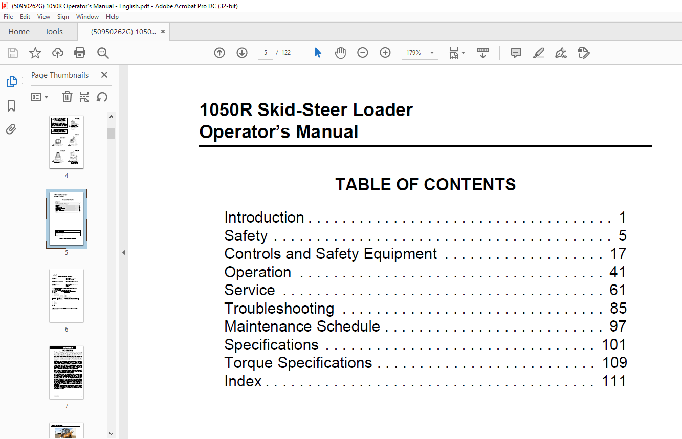
TABLE OF CONTENTS:
Mustang Manitou 1050R 1050R (EU) 1050R X-SERIES Skid-Steer Loader Operator’s Manual 50950262 – PDF DOWNLOAD
1050R Skid-Steer Loader Operator’s Manual 5
All-Tach™ and Hydraloc™ are trademarks of Manitou Group 5
Introduction 7
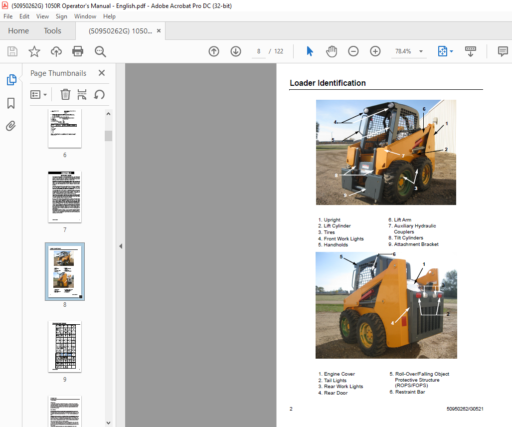
Loader Identification 8
1 Upright 8
2 Lift Cylinder 8
3 Tires 8
4 Front Work Lights 8
5 Handholds 8
6 Lift Arm 8
7 Auxiliary Hydraulic Couplers 8
8 Tilt Cylinders 8
9 Attachment Bracket 8
1 Engine Cover 8
2 Tail Lights 8
3 Rear Work Lights 8
4 Rear Door 8
5 Roll-Over/Falling Object Protective Structure (ROPS/FOPS) 8
6 Restraint Bar 8
Control/Indicator Symbols 9
Power Off 9
Power On 9
Engine Start 9
Battery Charge 9
Electrical Power 9
Worklight w/Tail Lights 9
Worklight 9
Safety Alert 9
Hazard Flasher 9
Fasten Seatbelt 9
Horn 9
Read Operator’s Manual 9
Volume – Full 9
Volume – Half Full 9
Volume – Empty 9
H-L 9
High – Low 9
N 9
Neutral 9
F 9
Forward 9
R 9
Reverse 9
Parking Brake 9
Engine Air Filter 9
Engine Oil 9
Engine Oil Filter 9
Engine Oil Pressure 9
Fuel Filter 9
Engine Temperature 9
Hydraulic System 9
Hydraulic Oil Temperature 9
Hydraulic Oil Filter 9
Grease Lubrication Point 9
Glow Indicator Lamp 9
Diesel Fuel 9
Chaincase Oil 9
Clockwise Rotation 9
Counterclockwise Rotation 9
Fast 9
Slow 9
Ride Control 9
Engine Malfunction Shutdown 9
Bucket – Float 9
Bucket – Rollback 9
Bucket – Dump 9
Lift Arm – Lower 9
Lift Arm – Raise 9
Service Hours 9
Control/Indicator Symbols, cont 10
Battery Disconnect 10
DPF Service 10
Exhaust Gas Temperature 10
DPF Regen Acknowledgement 10
Service Interval 10
Low Fuel Alarm 10
Master Light Switch 10
Position Lights 10
Engine Speed Control 10
DPF Regen Inhibited 10
Self-Leveling 10
Unlock 10
Lift Point 10
Windshield Washer 10
Rear Washer 10
Windshield Wiper 10
Rear Wiper 10
Fan 10
Heater 10
Temperature 10
Beacon 10
Lock 10
Aftertreatment Error 10
Safety 11
Mandatory Safety Shutdown Procedure 12
1 Move the drive control handle(s) to the neutral position 12
2 Lower the lift arm and attachment completely If the lift arm must be left in the raised position, be sure to properly engage the lift arm support device (page 21) 12
3 Move the throttle to the low idle position, shut off the engine and remove the key 12
4 Before exiting, move the lift/tilt control(s) to verify that the controls do not cause movement of the lift arm and hitch 12
Safety Reminders 12
Potential Hazards 14
Safety Decals 15
Safety Decals inside the ROPS/FOPS 16
Safety Decals on the outside of the Skid Loader 17
Safety Decals in the Engine Compartment 18
ISO-Style (used Internationally) Safety Decals inside the ROPS/FOPS 19
ISO-Style (used Internationally) Safety Decals on the outside of the Skid-Steer Loader 20
ISO-Style (used Internationally) Safety Decals in the Engine Compartment 21
Product and Component Plate Locations 22
Controls and Safety Equipment 23
Guards and Shields 23
Operator Restraint Bar 23
Operator’s Seat 24
Figure 1 Operator’s Seat 24
1 Restraint Bar 24
2 Seatbelt 24
3 Seat Adjustment Level 24
Upper-Torso Restraint 24
Safety Interlock System 24
ROPS/FOPS 25
Parking Brake 26
Figure 2 Parking Brake Switch – DPF Models above, Non-DPF Models below 26
Horn 26
Rear Window Emergency Exit 26
Figure 3 Rear Window Emergency Exit 26
1 Pull Tag 26
Lift Arm Support Device 27
1 Lower the lift arm fully 27
Figure 4 Lift Arm Support Device Engaged 27
2 Stop the engine 27
3 Have an assistant remove the lift arm support device from its storage location (Figure 4) on the left side of the machine Remove the lynch pin holding the support device up against the lift arm Allow the support device to come down into contact 27
4 Restart the engine 27
5 Use the lift control to raise the lift arm until the support device drops over the end of the lift cylinder and around the cylinder rod Slowly lower the lift arm until the free-end of the support device contacts the top end of the lift cylinder 27
6 Look to be sure the support device is secure against the cylinder end Then, stop the loader engine, remove the key and exit the operator’s compartment 27
Figure 5 Lock Pin in storage Position 28
1 Start the engine 28
2 Raise the lift arm fully 28
3 Stop the engine 28
4 Verify that the lift arm is being held in the raised position by the safety interlock system 28
5 To store the support device, have an assistant raise it up until it contacts the lift arm Reinstall the lynch pin through the welded steel post on the lift arm (Figure 5) 28
Accessory Plug 28
Dome Light 28
Work Lights 28
Heater (optional) 28
1 Fan Speed Control Knob: Controls the fan speed and turns the heater system on or off 28
2 Temperature Control: The rotary knob regulates the temperature of the heated air Rotate clockwise to increase the temperature; counterclockwise to decrease the temperature 28
Lockable Fuel Cap 29
1 Shut off the engine and remove the key Insert the fuel cap key into the fuel cap lock 29
2 Turn the key 45° clockwise to unlock the fuel cap and turn the cap off the fuel fill neck When finished fueling the loader, replace the cap and tighten it Holding the cap, insert the key and turn it 45° counterclockwise to lock the cap in plac 29
Engine Speed Control 30
Figure 6 Engine Speed Control – DPF Models above, Non-DPF Models below 30
Figure 7 Foot Throttle – DPF Models above, Non-DPF Models below 30
Float Control 31
Instrument Panel (DPF Models) 32
Figure 8 Instrument Panel 32
1 Keyswitch – In a clockwise rotation, these positions are: 32
2 Information Center Electronic Display – See page 29 32
3 Fuel Level Gauge – Displays the amount of fuel in the tank 32
4 Fasten Seatbelt – A momentary visual (and audible) indicator to remind the operator to fasten the seatbelt 32
5 Engine Oil Pressure – Lights if the engine oil pressure drops too low, warning the operator to immediately stop the engine and determine the cause for the pressure drop During normal operation, this indicator should be OFF 32
6 Battery – Lights if the charging voltage is too high or too low During normal operation, this indicator should be OFF 32
7 Preheat Indicator Lamp – Lights when the (automatic) preheat is active During normal operation this indicator should be OFF 32
8 Engine Malfunction Lamp – Indicates the engine ECU has detected a malfunction of the engine 33
9 Engine Coolant Temperature – Lights if the engine coolant becomes too hot, warning the operator to stop the engine Allow the engine to cool, determine the cause for the high temperature and correct the problem before restarting the engine Duri 33
10 Hydraulic Oil Temperature – Lights if the hydraulic oil becomes too hot, warning the operator to stop engine Allow the hydraulic system to cool and determine the cause of the high temperature During normal operation, this indicator should be OFF 33
11 Parking Brake Switch – Used to manually apply the parking brake Lights when the parking brake is applied 33
12 Engine Speed Control – Controls the engine speed Move the control clockwise to increase and counter-clockwise to decrease the engine speed 33
13 Light Switch – Controls all the lights on the loader Symbols denote the four positions of the light switch In a clockwise direction these are: 33
14 Accessory Outlet – 12-volt DC power outlet 33
Instrument Panel (Non-DPF Models) 34
Figure 9 Instrument Panel 34
1 Hourmeter – Displays the total operating hours on the loader 34
2 Fuel Level Gauge – Displays the amount of fuel in the tank 34
3 Engine Coolant Temperature Gauge – Indicates the engine coolant temperature 34
4 Fasten Seatbelt – A momentary visual (and audible) indicator to remind the operator to fasten the seatbelt 34
5 Engine Oil Pressure – Lights if the engine oil pressure drops too low, warning the operator to immediately stop the engine and determine the cause for the pressure drop During normal operation, this indicator should be OFF 34
6 Battery – Lights if the charging voltage is too high or too low During normal operation, this indicator should be OFF 34
7 Preheat Indicator Lamp – Lights when the preheat switch is pressed During normal operation, this indicator should be OFF 34
8 Engine Coolant Temperature – Lights if the engine coolant becomes too hot, warning the operator to stop the engine Allow the engine to cool, determine the cause for the high temperature and correct the problem before restarting the engine Duri 34
9 Hydraulic Oil Temperature – Lights if the hydraulic oil becomes too hot, warning the operator to stop engine Allow the hydraulic system to cool and determine the cause of the high temperature During normal operation, this indicator should be OFF 34
10 Keyswitch – In a clockwise rotation, these positions are: 35
11 Parking Brake Switch – Used to manually apply the parking brake The red indicator on the switch lights when the parking brake is applied 35
12 Light Switch – Controls all the lights on the loader Symbols denote the four positions of the light switch In a clockwise direction these are: 35
13 Circuit Breakers – Four circuit breakers on the instrument panel protect the loader’s electrical circuits 35
14 Accessory Outlet – 12-volt DC power outlet 35
T-Bar Controls 36
Figure 10 T-Bar Controls 36
1 Drive Control 36
2 Lift/Tilt Control 36
Hand/Foot Controls 37
Figure 11 Hand/Foot Controls 37
1 Left Drive Control Handle 37
2 Right Drive Control Handle 37
3 Tilt Control Foot Pedal 37
4 Lift Control Foot Pedal 37
Auxiliary Hydraulic Controls 38
Figure 12 Auxiliary Couplers 38
Figure 13 T-Bar Auxiliary Control 38
Figure 14 Hand/Foot Auxiliary Control 38
Attachment Mounting 39
Figure 15 All-Tach™ Attaching Mechanism (Hitch) 39
Electrical Battery Disconnect Switch (optional) 39
Figure 16 Battery Disconnect Switch 39
Information Center Electronic Display (DPF Models) 40
Figure 17 – Information Center Electronic Display 40
Information Center Electronic Display Symbols 41
Table 1: Symbols Descriptions 41
Information Center Electronic Display Screens 43
Table 2: Status, Maintenance and Error Code Screens 43
Operation 47
Before Starting the Engine 47
Fuel 47
Starting the Engine 47
1 Carefully step up onto the back of the bucket or attachment and grasp the handholds to enter the operator’s compartment 47
2 Close the door, fasten the seatbelt(s) and lower the restraint bar 47
3 Verify the following: 47
4 Turn the key to the START position 48
Cold-Starting 48
Cold Starting Procedure 48
1 Turn the key to the RUN position If the preheat light on the right instrument panel comes on, wait for this symbol to go out 48
2 Immediately turn the key to the START position 48
3 If engine does not start, return key to OFF position and repeat steps 1 and 2 48
Stopping the Loader 49
1 Check that the drive control handle(s) is (are) in neutral position 49
2 Lower the lift arm and rest the attachment on the ground 49
3 Turn throttle knob back to the low idle position (and release the throttle pedal for T-bar control machines) Allow the engine to idle for five minutes if the engine was operated under full load 49
4 Turn the keyswitch to the OFF position and remove the key 49
5 Move the lift/tilt control to verify that the safety interlock system is preventing movement 49
6 Raise the restraint bar, unfasten the seatbelt(s) and grasp the handholds while climbing out of the operator’s compartment 49
Parking the Loader 50
Jump Starting the Engine 50
1 Turn the keyswitches of both vehicles to OFF, be sure the vehicles are in “neutral” and NOT touching each other 50
2 Connect the positive (+) jumper cable to the positive (+) battery terminal on the disabled loader first DO NOT allow the positive clamps to touch any metal other than the positive (+) battery terminals 50
3 Connect the other end of the positive jumper cable to the jumper vehicle’s battery positive (+) terminal 50
4 Connect the negative (-) jumper cable to the jumper vehicle’s battery negative (-) terminal 50
5 Make the final negative (-) jumper cable connection to the disabled loader’s engine block or loader frame (ground), such as the rear grille latch post – NOT to the disabled battery’s negative post If connected to the engine, keep the jumper 50
6 Start the loader If it does not start at once, start the jumper vehicle engine to avoid excessive drain on the booster battery 50
7 After the disabled loader is started and running smoothly, have the second person remove the jumper cables (negative (-) jumper cable first) from the jumper vehicle’s battery and then from the disabled loader while being sure NOT to short the tw 50
Changing Attachments 51
1 Rotate the latch levers to a vertical position to fully retract the latch pins 51
Figure 1 Hitch – disengaged 51
1 Latch Levers 51
2 Latch Pins 51
2 Start the loader engine and be sure the lift arm is lowered and in contact with the loader frame 51
3 Align the loader squarely with the back of the attachment 51
4 Tilt the hitch forward until the top edge of the hitch is below the flange on the back side of the attachment and centered between the vertical plates 51
5 Slowly drive the loader forward and, at the same time, tilt the hitch back to engage the flange on the back side of the attachment 51
6 Stop forward travel when the flange is engaged, but continue to tilt the hitch back to lift the attachment off the ground 51
7 Exercise the MANDATORY SAFETY SHUTDOWN PROCEDURE (page 6) 51
8 With the loader engine OFF, leave the operator’s compartment and rotate the latch levers all the way to the hitch to fully engage the latch pins 51
1 Tilt the hitch back until the attachment is off the ground 52
2 Exercise the Mandatory Safety Shutdown Procedure (page 6) 52
3 Relieve any hydraulic pressure in the auxiliary and attachment lines 52
a Turn the key swtich, but do not start the engine 52
b With the restraint bar down, move the auxiliary hydraulic control back and forth This will relieve the pressure in the hydraulic system 52
4 With the engine OFF, leave the operator’s compartment, disconnect the auxiliary hydraulic hoses and rotate the latch levers completely vertical to fully retract the latch pins 52
5 Start the engine and be sure that the lift arm is fully lowered and in contact with the loader frame 52
6 Tilt the hitch forward and slowly back the loader away until the attachment is free from the loader 52
Self-Leveling (optional) 52
Using a Bucket 52
Figure 2 Loading 53
Figure 3 Digging 53
Figure 4 Dumping Into a Box 54
Figure 5 Scraping 54
Figure 6 Leveling the Ground 54
Vibration Information 55
Vibration Measurement and Actions 56
1 Train operators 56
2 Choose proper equipment for the job 56
3 Maintain the work site 56
4 Maintain the equipment 56
Highway Travel 57
Lifting the Loader 58
1 Using suitable lift equipment, hook into the lift eyes Adjust the length of the slings or chains to lift the loader level 58
2 Center the hoist over the ROPS/FOPS To prevent shock loading of the equipment and excessive swinging, slowly lift the loader off the ground Perform all movements slowly and gradually As needed, use a tag line to help position the loader and kee 58
Storing the Loader 58
1 Fully inflate the tires 58
2 Lubricate all grease zerks 58
3 Check all fluid levels and replenish as necessary (Review and follow the engine manufacturers recommendations from the Engine Operator’s Manual ) 58
4 Add stabilizer to the fuel per the fuel supplier’s recommendations If the fuel has a mixture of BioDiesel, empty the fuel tank before storing 58
5 Turn the electrical battery disconnect switch to its OFF position and remove the battery, charge it fully and store in a cool, dry location 58
6 Protect against extreme weather conditions such as moisture, sunlight and temperature 58
Removing Loader from Storage 59
1 Check the tire air pressure and inflate the tires if they are low 59
2 Connect the battery and check that the electrical battery disconnect switch is turned to its ON position 59
3 Check all fluid levels (engine oil, transmission/hydraulic oil, engine coolant and any attached implements) (Review and follow the engine manufacturers recommendations from the Engine Operator’s Manual ) 59
4 Start the engine Observe all gauges If all gauges are functioning properly and reading normal, move the machine outside 59
5 Once outside, park the machine and let the engine idle for at least five minutes 59
6 Shut the engine off and walk around machine Make a visual inspection looking for evidence of leaks 59
Transporting/Towing the Loader 60
Figure 7 Front Tie Down/Retrieval point 60
1 Block the front and rear of the hauling vehicle’s tires 60
2 If the loader has an attachment, lift it slightly off the ground 60
3 Back the loader slowly and carefully up the ramp onto the vehicle 60
4 Lower the loader attachment to the vehicle deck, turn off the engine and remove the key 60
Figure 8 Rear Tie Down/ Retrieval point 60
5 Fasten the loader to the hauling vehicle at the points indicated by the tie- down decals (Figure 7 and Figure 8) 60
6 Measure the clearance height of the loader and hauling vehicle Post the clearance height in the cab of the vehicle 60
1 Connect the towline to both tie down/retrieval points at the front or the rear of the loader Use of only a single retrieval point or connecting the towline to any point on the loader other than the designated retrieval locations could result in l 60
2 The towline strength is at least 1 5 times the gross weight of the loader The towline length is such that the maximum towing angle does not exceed 20° 60
Diesel Particulate Filter (DPF) Regeneration Procedures (DPF Models) 61
Reset Regeneration 62
Figure 9 – Reset Regeneration In- Progress 62
Figure 10 – Reset Regeneration Inhibit Button 62
Stationary Regeneration 63
Figure 11 – Stationary Regeneration Request Screen 63
Figure 12 – Stationary Regeneration 63
1 Park the machine in a safe, well- ventilated location away from flammable materials 63
2 The following conditions need to be met before stationary regeneration continues: 63
3 When all three checkmarks (A, B & C) are displayed on the Stationary Regeneration screen, press and hold the button (Z) until the Stationary Regeneration In-Progress screen displays (Figure 13) 64
Figure 13 – Stationary Regeneration In-Progress Screen 64
Forcing Stationary Regeneration 64
Figure 14 – Forcing Stationary Regeneration 64
DPF Maintenance 65
Figure 15 – DPF Service Screen 65
Back-Up Alarm 65
Notes 66
Service 67
Dealer Services 67
Figure 1 Engine Compartment – DPF Models 67
1 Air Cleaner 67
2 Exhaust Tube 67
3 Radiator/Cooler 67
4 Coolant Recovery Tank 67
5 Hydraulic Oil Filter 67
6 Engine Oil Dipstick 67
7 Engine Oil Fill Cap 67
8 Engine Oil Filter 67
9 Fuel Filter 67
10 Fuel Pump 67
11 Water Trap 67
12 DPF Cannister 67
Figure 2 Engine Compartment – Non-DPF Models 68
1 Air Cleaner 68
2 Muffler 68
3 Radiator/Cooler 68
4 Coolant Recovery Tank 68
5 Hydraulic Oil Filter 68
6 Engine Oil Dipstick 68
7 Engine Oil Fill Cap 68
8 Engine Oil Filter 68
9 Fuel Filter 68
10 Fuel Pump 68
11 Water Trap 68
Tilting Back the ROPS/FOPS 68
Figure 3 ROPS Lock Mechanism 68
Loader Raising Procedure 68
1 Using a jack or hoist capable of lifting the fully-equipped weight of the loader (with all attached options), lift the rear of the loader until the rear tires are off the ground 69
2 Stack wooden blocks under the flat part of the loader chassis They should run parallel with, but not touch, the rear tires (Figure 4) 69
3 Slowly lower the loader until its weight rests on the blocks If the tires still touch the ground, raise the loader again, add more blocks and lower again 69
4 Repeat Steps 1 through 3 for the front end When the procedure is finished, all four tires will be off the ground so they can be removed 69
Loader Lowering Procedure 69
1 Using a jack or hoist, raise the front of the loader until its weight no longer rests on the front blocks 69
2 Carefully remove the blocking under the front of the loader 69
Figure 4 Blocked Loader 69
3 Slowly lower the loader until the front tires are resting on the ground 69
4 Repeat Steps 1 through 3 for the rear of the loader When the procedure is finished, all four tires will be on the ground and the blocks removed from under the loader 69
Replacement Parts 69
188814 69
188817 69
074830 69
195568 69
50352551 69
50352550 69
137500 69
182130 69
Adjustments 70
Removing Foreign Material 70
Lubrication 71
Figure 5 Grease Every 10 Hours (or daily) 72
1 Lift arm pivots (2) 72
2 Lift cylinder pivots (4) 72
3 Tilt cylinder pivots (2) 72
4 Attachment Bracket pivots (2) 72
Figure 6 Service Locations (see Maintenance Chart on page 97 ) 73
l 73
l 73
l 73
l 73
l 73
l 73
l 73
l 73
u 73
u 73
l 73
l 73
Engine Air Cleaner 74
Figure 7 Dual-Element Air Cleaner – DPF Models 74
1 Restriction Indicator 74
2 Element Housing 74
3 Elbow Hose 74
4 Hose Connector 74
5 Sound Diffuser/Intake Suppressor 74
6 Air Intake Tube 74
Figure 8 Dual-Element Air Cleaner – Non-DPF Models 74
1 Restriction Indicator 74
2 Element Housing 74
3 Inner Filter Element 74
4 Outer Filter Element 74
5 Element Cover 74
6 Dust Ejector 74
1 Open the rear door and engine access cover 75
2 Unlatch the clamps on the air cleaner and remove the cover Clean out any dirt built up in the cover assembly 75
1 Carefully pull the outer element out of the housing Never remove the inner element unless it is to be replaced 75
2 Clean out any dirt built up in the housing Leave the inner element installed during this step to prevent debris from entering the engine intake manifold 75
3 Replace the outer element 75
4 Use a trouble light inside the outer element to inspect for spots, pinholes or ruptures Replace the outer element if any damage is noted The outer element must be replaced if it is oil- or soot-laden 75
1 Before removing the inner element from the housing, clean out any dirt built up in the housing Leave the inner element installed during this step to prevent debris from entering the engine intake manifold 75
2 Remove the inner element 75
1 Check the inside of the housing for any damage that may interfere with the elements 75
2 Be sure that the element sealing surfaces are clean 75
3 Insert the element(s), making sure that they are seated properly 75
4 Secure the cover to the housing with clamps 75
5 Check the hose connections and be sure they are all clamped and tightened properly 75
6 Reset the restriction indicator by pressing the reset button 75
Engine Service 76
Figure 9 Oil Dipstick and Fill Cap – DPF Models 76
1 Oil Dipstick 76
2 Oil Fill Cap 76
Figure 10 Oil Dipstick and Fill Cap – Non-DPF Models 76
1 Oil Dipstick 76
2 Oil Fill Cap 76
1 Run the engine until it is at operating temperature Stop the engine Remove the rear belly pan 77
Figure 11 Rear Belly Pan 77
2 Remove the drain plug 77
3 From the engine compartment, remove the oil filter Clean the filter sealing surface 77
4 Put clean oil on the new oil filter gasket Install the filter and tighten 3/4 of a turn past the point where the gasket contacts the filter head 77
5 Reinstall and tighten the drain plug 77
6 Remove the oil cap and add the recommended oil Refer to the “Lubrication” topic in this chapter for oil specifiactions and capacities 77
7 Start the engine and let it run for several minutes at low idle Stop the engine Check for leaks at the oil filter, drain plug and remote oil drain hose Check the oil level Add oil if it is not at the top mark on the dipstick 77
1 Shut off the fuel supply by turning the fuel shutoff valve on top of the water trap 77
2 Non-DPF Models: Shut off the return line by turning the valve on the fuel tank 77
3 Remove the fuel filter element 77
4 Lubricate new fuel filter element gasket with diesel fuel 77
5 Install and tighten the filter element one-half turn past point the where the gasket contacts the filter head 77
6 Turn shutoff valve on water separator to on 77
7 Non-DPF Models: Turn on the fuel supply at the fuel tank 77
Figure 12 Location of Water Separator 78
1 Shut off the fuel supply by turning the fuel shutoff valve on top of the water separator 78
2 Turn nut to release the bowl from the valve head Dispose remaining fuel and water 78
3 Clean bowl and filter element with warm water until all foreign material is removed Replace fuel filter if damaged Refer to Parts Manual for part number 78
4 Place element onto valve head Lubricate o-ring on bowl with diesel fuel and place on valve head Turn nut to tighten 78
5 Turn on fuel supply 78
Spark Arrestor Muffler (Non-DPF Models) 79
1 Stop the engine, open the rear door and engine cover 79
2 Remove the plug from the bottom of the muffler 79
3 Block the outlet of the muffler with a non-combustible material 79
4 Start the engine and run it for 10-15 seconds 79
5 Stop the engine and remove the blockage 79
6 Put anti-seize coating on the plug 79
7 Reinstall and tighten the plug 79
1 Check red float located in the water separator bowl If red float is raised, open valve on the bottom of the bowl to drain water 79
2 Close valve quickly after float reaches the bottom of the bowl 79
Alternator/Fan Belt 79
Engine Diagnostic Chart (DPF Models) 79
Figure 13 Data Port for the Engine 79
Hydraulic System 84
Figure 14 Hydraulic Oil Service 84
1 Open the rear door and engine cover to access the filter Unscrew the filter 84
Figure 15 Drain Plug 84
2 Clean the surface of the filter housing where the element seal contacts the housing Put clean oil on the rubber gasket of the new filter element 84
3 Install and tighten the filter element 3/4 of a turn past the point where the gasket contacts the filter head 84
4 For a replacement element, refer to the Replacement Parts topic (page 63) 84
1 Remove the oil filler cap 84
2 Install a catch pan of sufficient capacity under the oil reservoir (8 gallons [30 liters]) 84
3 Remove the drain plug located on the bottom left of the oil reservoir 84
4 Remove and replace the hydraulic oil filter 84
5 Reinstall the drain plug 84
6 Refill the reservoir until the oil is between the two lines on the dipstick gauge 84
7 Start the engine and operate the hydraulic controls 84
8 Stop the engine and check for leaks at the filter and reservoir drain plug 84
9 Check the fluid level and add fluid if needed 84
Cooling Systems 85
1 Open the rear door Check the coolant level in the coolant recovery tank on the inside of the rear door The coolant recovery tank must be 1/3 to 1/2 full with a cold engine and 2/3 to 3/4 full with a hot engine 85
Figure 16 Cooling System 85
1 Recovery Tank 85
2 Radiator/Cooler 85
3 Drain Plug 85
2 Allow the coolant to cool Do not remove the cap when the coolant is hot Serious burns may occur 85
3 Add premixed coolant, 50% water and 50% ethylene glycol, to the recovery tank if the coolant level is low 85
1 Park the loader on a level surface, lower the lift arm and stop the engine Allow the engine to cool 85
2 Open the rear door Lift the engine cover 85
3 Clean the radiator and oil cooler by blowing through the fins with high pressure water or air 85
1 Open the rear door Lift the engine cover 85
2 Slowly remove the radiator cap, allowing pressure to dispel before removing completely 85
3 Remove the drain plug and drain the coolant into a suitable container 85
4 Replace the drain plug 85
5 Fill the radiator fully and the recovery tank half full with the premixed coolant 86
6 Reinstall the radiator cap 86
7 Run the engine until it is at operating temperature Stop the engine and let it cool Check the coolant level Add more coolant if required 86
Chaincases 86
1 Park the loader on a level surface Stop the engine 86
Figure 17 Check Plug 86
2 Remove the check plug from each chaincase housing If the oil can be reached with the tip of your finger, the oil level is adequate 86
3 If the level is low, add fluid through the check plug until the oil level reaches the edge of the hole Reinstall the check plug 86
1 Raise the rear of the machine to aid in draining the chaincases 86
Figure 18 Right side drain plug (left side same) 86
2 Remove the drain plug on each chaincase and drain the oil into a suitable container 86
3 Reinstall and tighten the drain plugs 86
4 Refill the chaincases at the check plugs 86
Seat and Restraint Bar Switches 87
Bucket Cutting Edge 87
Wheel Nuts 87
Tires 87
1 Be sure the rim is clean and free of rust 87
2 Lubricate the tire beads and rim flanges with a soap solution Do not use oil or grease 87
3 Use a clip-on tire chuck with remote hose and gauge, allowing you to stand clear while inflating the tire Do not place your fingers on the tire bead or rim during inflation 87
4 Never inflate beyond 35 psi (240 kPa) to seat the beads If the beads have not seated by the time the pressure reaches 35 psi (240 kPa), deflate the assembly, reposition the tire on the rim, lubricate both parts and re-inflate Inflation pressure 87
5 After seating the beads, adjust the inflation pressure to the recommended operating pressure 87
6 Do not weld, braze or otherwise attempt to repair and use a damaged rim 87
Electrical System 88
1 Immediately remove any clothing on which acid spills 88
2 If acid contacts the skin, rinse the affected area with running water for 10 to 15 minutes 88
3 If acid contacts the eyes, flood the eyes with running water for 10 to 15 minutes See a doctor at once Never use any medication or eye drops unless prescribed by the doctor 89
4 To neutralize acid spilled on the floor, use one of the following mixtures: 89
a 1 pound (0 5 kg) of baking soda in 1 gallon (4 L ) of water 89
b 1 pint (0 5 L) of household ammonia in 1 gallon (4 L) of water 89
Figure 19 Fuse Panels in the Engine Compartment 89
Figure 20 Fuse Panel in the ROPS/FOPS Compartment 89
Troubleshooting 91
Maintenance Schedule 103
l 103
l 103
l 103
l 103
l 103
l 103
l 103
l 103
l 103
l 103
m 103
l 103
l 103
o l 103
l 103
l 103
l 103
l 103
l* 103
l 103
u 103
u 103
l 103
Specifications 107
Loader Specifications 107
Standard Features 108
Optional Features 108
Dimensional Specifications 109
1050R 109
10 5 ft3 (0 3 m3) Bucket w/27 x 8 5 x 15 Tires 109
inches 109
mm 109
A 109
142 109
3607 109
B 109
107 5 109
2731 109
C 109
70 3 109
1786 109
D 109
118 109
2997 109
E 109
40o 109
F 109
82 109
2083 109
G 109
25 25 109
641 109
J 109
31o 109
M 109
101o 109
O 109
32 5 109
826 109
P 109
34 5 109
876 109
Q 109
48 5/57 109
1232/1448 109
R 109
55 3 109
1404 109
S 109
6 25 109
159 109
V 109
88 5 109
2248 109
W 109
22o 109
X 109
72 109
1829 109
Y 109
42 109
1067 109
Z 109
54 109
1372 109
Capacities and Ratings 110
Weight 110
Rated Operating Capacity 110
1050R 110
235 lbs (107 kg) 110
1095 lbs (497 kg) 110
252 lbs (114 kg) 110
881 lbs (340 kg) 110
253 lbs (115 kg) 110
1082 lbs (491 kg) 110
254 lbs (115 kg) 110
1061 lbs (481 kg) 110
383 lbs (174 kg) 110
975 lbs (422 kg) 110
313 lbs (142 kg) 110
1061 lbs (481 kg) 110
335 lbs (152 kg) 110
826 lbs (375 kg) 110
395 lbs (179 kg) 110
795 lbs (361 kg) 110
331 lbs (150 kg) 110
1228 lbs (557 kg) 110
470 lbs (213 kg) 110
662 lbs (300 kg) 110
470 lbs (213 kg) 110
616 lbs (279 kg) 110
470 lbs (213 kg) 110
575 lbs (261 kg) 110
Table of Common Materials and Densities 111
Material 111
Density 111
lbs/ft3 111
kg/m3 111
35-50 111
560-800 111
112 111
1792 111
110 111
1760 111
23 111
368 111
80-100 111
1280-1600 111
53-63 111
848-1008 111
115 111
1840 111
50 111
800 111
94 111
1504 111
30 111
480 111
70-90 111
1121-1442 111
80-100 111
1281-1602 111
93-111 111
1488-1776 111
100 111
1602 111
120 111
1922 111
115 111
1840 111
145 111
2320 111
60 111
960 111
90 111
1440 111
65 111
1040 111
45 111
720 111
47 111
752 111
90 111
1440 111
68 111
1088 111
110 111
1760 111
100 111
1602 111
135 111
2160 111
108 111
1728 111
125 111
2000 111
95 111
1520 111
90 111
1440 111
70 111
1120 111
15-50 111
240-800 111
107 111
1712 111
Bucket Selections 112
Torque Specifications 115
8-32 115
8-36 115
10-24 115
10-32 115
19* 115
20* 115
27* 115
31* 115
14* 115
15* 115
21* 115
23* 115
30* 115
31* 115
43* 115
49* 115
22* 115
23* 115
32* 115
36* 115
41* 115
43* 115
60* 115
68* 115
31* 115
32* 115
45* 115
51* 115
1/4-20 115
1/4-28 115
5/16-18 115
5/16-24 115
66* 115
76* 115
11 115
12 115
50* 115
56* 115
9 115
9 115
9 115
10 115
17 115
19 115
75* 115
86* 115
13 115
14 115
12 115
14 115
25 115
25 115
9 115
10 115
18 115
20 115
3/8-16 115
3/8-24 115
7/16-14 115
7/16-20 115
20 115
23 115
32 115
36 115
15 115
17 115
24 115
27 115
30 115
35 115
50 115
55 115
23 115
25 115
35 115
40 115
45 115
50 115
70 115
80 115
35 115
35 115
55 115
60 115
1/2-13 115
1/2-20 115
9/16-12 115
9/16-18 115
50 115
55 115
70 115
80 115
35 115
40 115
55 115
60 115
75 115
90 115
110 115
120 115
55 115
65 115
80 115
90 115
110 115
120 115
150 115
170 115
80 115
90 115
110 115
130 115
5/8-11 115
5/8-18 115
3/4-10 115
3/4-16 115
100 115
110 115
175 115
200 115
75 115
85 115
130 115
150 115
150 115
180 115
260 115
300 115
110 115
130 115
200 115
220 115
220 115
240 115
380 115
420 115
170 115
180 115
280 115
320 115
7/8-9 115
7/8-14 115
1-8 115
1-12 115
170 115
180 115
250 115
270 115
125 115
140 115
190 115
210 115
430 115
470 115
640 115
710 115
320 115
360 115
480 115
530 115
600 115
660 115
900 115
1000 115
460 115
500 115
680 115
740 115
M6-1 115
M8-1 25 115
M10-1 5 115
8 115
19 115
37 5 115
6 115
14 115
28 115
11 115
27 115
53 115
8 115
20 115
39 115
13 5 115
32 5 115
64 115
10 115
24 115
47 115
M12-1 75 115
M14-2 115
M16-2 115
65 115
103 5 115
158 5 115
48 115
76 5 115
117 5 115
91 5 115
145 5 115
223 5 115
67 5 115
108 115
165 5 115
111 5 115
176 5 115
271 115
82 115
131 115
200 115
INDEX 117
Blank Page 0
Blank Page 0
Blank Page 113
Blank Page 114
IMAGES PREVIEW OF THE MANUAL:
VIDEO PREVIEW OF THE MANUAL:
PLEASE NOTE:
- This is the same manual used by the DEALERSHIPS to SERVICE your vehicle.
- The manual can be all yours – Once payment is complete, you will be taken to the download page from where you can download the manual. All in 2-5 minutes time!!
- Need any other service / repair / parts manual, please feel free to contact us at heydownloadss @gmail.com . We may surprise you with a nice offer
S.V


