
Mustang 4000V 4000V (EU) Skid-Steer Loader Operator’s Manual 50950005 CP0714 – PDF DOWNLOAD
FILE DETAILS:
Mustang 4000V 4000V (EU) Skid-Steer Loader Operator’s Manual 50950005 CP0714 – PDF DOWNLOAD
Language : English
Pages : 118
Downloadable : Yes
File Type : PDF
Size: 17.8 MB
DESCRIPTION:
Mustang 4000V 4000V (EU) Skid-Steer Loader Operator’s Manual 50950005 CP0714 – PDF DOWNLOAD
INTRODUCTION”
- This Operator’s Manual provides the owner/operator with information for operating,
maintaining and servicing model 4000V skid-steer loaders. More important,
this manual provides an operating plan for safe and proper use of the machine.
Major points of safe operation are detailed in the Safety chapter of this manual. - Users should read and understand the contents of this manual completely and
become familiar with the machine before operating it. Contact your authorized
Mustang dealer if you have any questions concerning information in this manual,
require extra manuals, and for information concerning the availability of manuals
in other languages. - Throughout this manual information is provided set in italic type and introduced
by the word Note or Important. Read carefully and comply with those messages
– it will improve operating and maintenance efficiency, help avoid breakdowns
and damage, and extend the machine’s life. - A manual storage box in the operator’s compartment behind the seat holds the
Operator’s Manual and AEM Safety Manual (also available in Spanish). Please
return the manuals to this box and keep them with the unit at all times. If this
machine is resold, these manuals should be given to the new owner. - The attachments and equipment available for use with this machine have a wide
variety of applications. Read the manual provided with the attachment to learn
how to safely maintain and operate the equipment. Be sure the machine is suitably
equipped for the type of work to be performed. - Do not use this machine for any applications or purposes other than those
described in this manual or those applicable for approved attachments. If the
machine is to be used with special attachments or equipment other than those
approved by Manitou Americas, consult your Mustang dealer. Any person using
non-approved attachments or making unauthorized modifications is responsible
for the consequences. - The Mustang dealership network stands ready to provide any assistance that may
be required, including providing genuine Mustang service parts. All service parts
should be obtained from your Mustang dealer. Provide complete information
about the part and include the model and serial numbers of the machine. Record
these numbers in the space provided on the Table of Contents page as a handy
reference. - Please be aware that Manitou Americas strives to continuously improve its products
and reserves the right to make changes and improvements in the design and
construction of any part without incurring the obligation to install such changes
on any previously delivered unit. - If this machine was purchased “used,” or if the owner’s address has changed,
please provide your Mustang dealer or Mustang Service Department with the
owner’s name and current address, along with the machine model and serial
number. This will allow the registered owner information to be updated, so that
the owner can be notified directly in case of an important product issue, such as a
safety update program.
TABLE OF CONTENTS:
Mustang 4000V 4000V (EU) Skid-Steer Loader Operator’s Manual 50950005 CP0714 – PDF DOWNLOAD
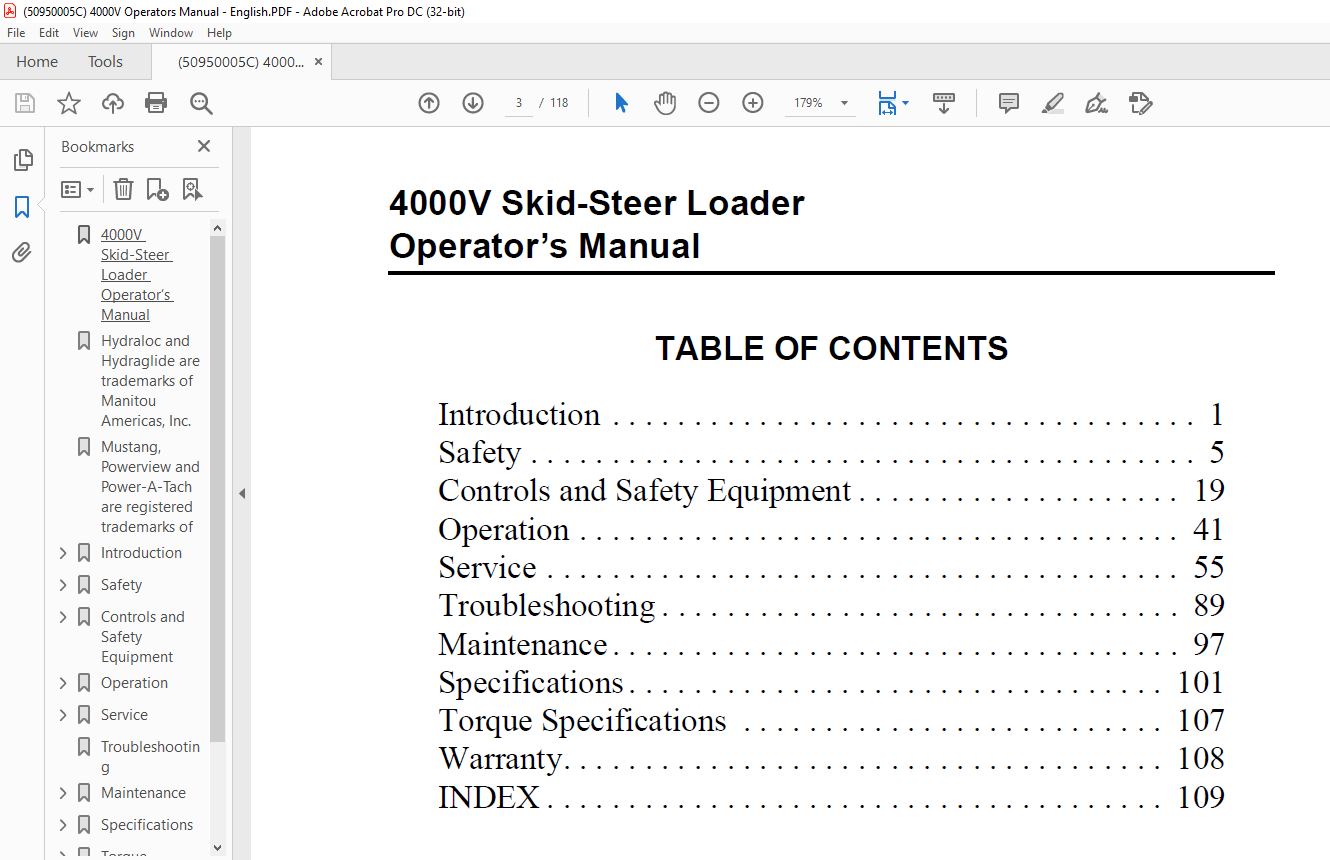
4000V Skid-Steer Loader Operator’s Manual 3
Hydraloc and Hydraglide are trademarks of Manitou Americas, Inc 3
Mustang, Powerview and Power-A-Tach are registered trademarks of Manitou Americas, Inc 3
Introduction 5
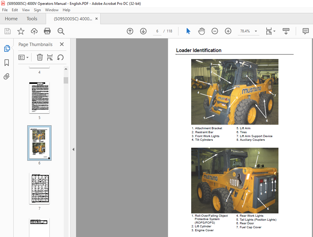
Loader Identification 6
1 Attachment Bracket 6
2 Restraint Bar 6
3 Front Work Lights 6
4 Tilt Cylinders 6
5 Lift Arm 6
6 Tires 6
7 Lift Arm Support Device 6
8 Auxiliary Couplers 6
1 Roll-Over/Falling Object Protective System (ROPS/FOPS) 6
2 Lift Cylinder 6
3 Engine Cover 6
4 Rear Work Lights 6
5 Tail Lights (Position Lights) 6
6 Rear Door 6
7 Fuel Cap Cover 6
Control/Indicator Symbols 7
Power Off 7
Power On 7
Engine Start 7
Battery Charge 7
Electrical Power 7
Worklight w/Tail Lights 7
Worklight 7
Safety Alert 7
Hazard Flasher 7
Fasten Seatbelt 7
Horn 7
Read Operator’s Manual 7
Volume – Full 7
Volume – Half Full 7
Volume – Empty 7
H-L 7
High – Low 7
N 7
Neutral 7
F 7
Forward 7
R 7
Reverse 7
Parking Brake 7
Engine Air Filter 7
Engine Oil 7
Engine Oil Filter 7
Engine Oil Pressure 7
Fuel Filter 7
Engine Temperature 7
Hydraulic System 7
Hydraulic Oil Temperature 7
Hydraulic Oil Filter 7
Grease Lubrication Point 7
Glow Indicator Lamp 7
Diesel Fuel 7
Chaincase Oil 7
Clockwise Rotation 7
Counterclockwise Rotation 7
Fast 7
Slow 7
Ride Control 7
Engine Malfunction Shutdown 7
Bucket – Float 7
Bucket – Rollback 7
Bucket – Dump 7
Lift Arm – Lower 7
Lift Arm – Raise 7
Service Hours 7
Lift Point 7
Tie-Down 7
Diesel Water Separator 7
Power-A-Tach® 7
Service Interval 7
Control/Indicator Symbols, cont 8
Low Fuel Alarm 8
Master Light Switch 8
Position Lights 8
Engine Speed Control 8
Safety 9
Mandatory Safety Shutdown Procedure 10
1 Move the drive control handle(s) to the neutral position 10
2 Lower the lift arm and attachment completely If the lift arm must be left in the raised position, be sure to properly engage the lift arm support device (page 22) 10
3 Move the throttle to the low idle position, shut off the engine and remove the key 10
4 Before exiting, move the lift/tilt control(s) to verify that the controls do not cause movement of the lift arm and hitch 10
Safety Reminders 10
Potential Hazards 12
Safety Decals 12
New Decal Application 12
ANSI-Style Safety Decals inside the ROPS/FOPS 13
ANSI-Style Safety Decals on the outside of the Loader 14
ANSI-Style Safety Decals on the outside of the Loader 15
ANSI-Style Safety Decals in the Engine Compartment 16
ISO-Style (used Internationally) Safety Decals inside the ROPS/FOPS 17
ISO-Style (used Internationally) Safety Decals on the outside of the Loader 18
ISO-Style (used Internationally) Safety Decals on the outside of the Loader 19
ISO-Style (used Internationally) Safety Decals in the Engine Compartment 20
Product and Component Plate Locations 21
Controls and Safety Equipment 23
Guards and Shields 23
Operator Restraint Bar 23
Operator’s Seat 24
Figure 1 Operator’s Seat 24
1 Restraint Bar 24
2 Seatbelt 24
3 Seat Position Adjustment Lever 24
4 Suspension Seat Weight Adjustment Knob (optional) 24
Upper-Torso Restraint 24
Safety Interlock System 24
Hydraloc™ 24
Testing the Safety Interlock System 25
ROPS/FOPS 25
Parking Brake 25
Figure 2 Parking Brake Switch 25
Horn 26
Rear Window Emergency Exit 26
Lift Arm Support Device 26
Installation 26
Figure 3 Lift Arm Support Device Engaged 26
1 Raise the lift arm to near full height 26
2 Stop the engine 26
3 Move the lift arm control to “lower” to verify that the lift arm is being held in the raised position by the safety interlock system 26
4 Have an assistant remove the lift arm support device from its storage location (Figure 4) on the left side of the machine and install the lift arm support device on the left lift cylinder (Figure 3) 26
5 Secure the support device to the lift cylinder rod with the attached lock pin and chain 26
6 Restart engine 27
7 Slowly lower the lift arm until it engages and locks against the lift arm support device 27
8 Stop the engine, and exit the machine 27
Removal 27
1 Start the engine; 27
2 Raise the lift arm fully; 27
3 Stop the engine; 27
4 Verify that the lift arm is being held in the raised position by the safety interlock system 27
Figure 4 Lift Arm Support Device Storage Location 27
5 Have an assistant remove the lift arm support device 27
6 Lower the lift arm and secure the lift arm support device with the lynch pin in the storage location (Figure 4) 27
Accessory Plug 27
Dome Light 28
Work Lights 28
Heater (optional) 28
1 Fan Speed Control: Controls the air flow 28
2 Temperature Control: The potentiometer switch is a rotary dial for control of heat functions 28
Heater and Air Conditioner (optional) 28
Figure 5 Heater/ Air Conditioner Controls 28
1 Fan Speed Control: Controls the air flow 28
2 Temperature Control: The potentiometer switch is a rotary dial for control of heat and air conditioning functions 28
Engine Speed Control 29
Figure 6 Engine Speed Control 29
Figure 7 Foot Throttle (Joystick controls) 29
Two-Speed Drive (Travel Mode Only) 29
Hydraglide™ Ride Control System 29
Float Control 30
Attachment Mounting 30
All-Tach® Hitch 30
Figure 8 All-Tach® Hitch 30
Power-A-Tach® System 30
Indicator and Warning Lamp Display 31
Figure 9 Indicator and Warning Lamp Display 31
Indicator and Warning Lamp Display 31
1 Battery – Lights if the charging voltage is too high or too low During normal operation this indicator should be OFF 31
2 Engine Air Filter – Lights when a restriction in the engine air filter is detected Warning the operator to clean or replace the element in the engine air cleaner During normal operation this indicator should be OFF 31
3 Hydraulic Oil Filter – Lights if the hydraulic filter becomes restricted, warning the operator to stop the engine, allow the engine to cool, and then change the oil and filter During normal operation this indicator should be OFF 31
4 Hydraulic Oil Temperature – Lights if the hydraulic oil is too hot, warning the operator to reduce the hydraulic load and determine the cause of the high temperature During normal operation this indicator should be OFF 31
5 High-Speed – Lights when two-speed is engaged 31
6 Hydraglide™ Ride Control System – Lights when the ride control system is activated 31
7 Float Indicator – Lights when the lift arm “float” function is activated 31
8 Fasten Seatbelt – A momentary visual (and audible) indicator to remind the operator to fasten the seatbelt(s) 31
9 Engine Malfunction Shutdown Indicator – Lights when the engine electronic control unit (ECU) has detected a failure warranting an automatic shutdown The indicator lamp also displays error codes when the key switch is turned to the “on” posi 31
Information Center Electronic Display 32
Figure 10 Information Center Electronic Display 32
Display Modes – Information Center Electronic Display 33
Single Screen 33
Bar Graph Limits Adjust 33
Dual Screen 33
Multi-Screen 33
DTC Screen 33
DTC Detailed Information 33
Settings Menu – Information Center Electronic Display 34
Display Mode 34
Language 34
Fuel Level Source 34
Alarm Output 34
Demo Mode 34
Tier4 Popout Mode 34
Contrast /Backlight 34
Units 34
Fuel Tank Calibration 34
Factory settings 34
Supported Parameters 34
Information Center Electronic Display (cont ) 35
Information Center Electronic Display (cont ) 36
Instrument Panels 37
Figure 11 Left Panel 37
Left Panel 37
1 Indicator and Warning Lamp Display – See page 27 37
2 Rotating Beacon/Strobe Switch (optional) – Controls the warning lamp (strobe or beacon) 37
3 Hazard/Flasher Switch (optional) – Controls hazard/flasher 37
4 High/Low Beam Switch (EU optional) – Controls road head lights between main/ upper beams and dimmed/lower beams Switch does not turn lights on or off 37
5 Turn Signal Switch (EU optional) – Used to turn on turn indicator lights Directional indicator lights are the same lights as the flashers The flashers will override the turn signals 37
6 High-Flow Auxiliary Switch (optional) – Controls the direction of hydraulic oil flow Push the right side of the rocker switch for forward flow, or the left side for reverse flow To disengage, push and release either side of the switch, or rais 37
7 Light Switch – Master control of the lights Push the right side of the rocker switch to activate front and rear lights, or to the left side for deactivation of the front and rear lights Also provides power to a machine equipped with flashers 37
8 Light Switch – Controls all the lights on the loader Push the rocker switch to the middle detent for front work lights and rear position lights Push the rocker switch fully to the right for front work lights and rear work lights operation 37
Figure 12 Lower Left Panel 37
Right Panel 38
Figure 13 Right Panel 38
1 Information Center Electronic Display – See page 28 38
2 Parking Brake Switch – Used to manually apply the parking brake Lights when the parking brake is applied 38
3 Front Wiper/Washer (optional) 38
4 Rear Wiper/Washer (optional) 38
5 Accessory Switch (optional) 38
6 Keyswitch – In a clockwise rotation, the positions are: 38
7 Power-A-Tach® System Switch – Used to actuate the Power-A-Tach® System Press the top of the switch to retract (release) the hitch pins; press the bottom of the switch to extend (engage) the hitch pins (see page 26) 38
8 Engine Speed Control – Controls the engine speed Move the control clockwise to increase and counter-clockwise to decrease the engine speed 38
Joystick Controls 39
Figure 14 Dual Joystick Controls 39
1 Lift/Tilt Control 39
2 Drive Control 39
Drive Controls 39
Lift/Tilt Control 40
Hand/Foot Controls 41
Figure 15 Hand/Foot Controls 41
1 Left Drive Control Handle 41
2 Right Drive Control Handle 41
3 Lift Control Pedal 41
4 Tilt Control Pedal 41
Drive Controls 41
Lift/Tilt Controls 42
Auxiliary Hydraulic System 43
Standard-Flow Auxiliary Hydraulic Control 43
Figure 16 Joystick Electric Auxiliary Control 43
High-Flow Auxiliary Hydraulic Control (Optional) 44
Figure 17 High-Flow Auxiliary Switch 44
Battery Disconnect Switch 44
Figure 18 Battery Disconnect Switch 44
Operation 45
Before Starting the Engine 45
Fuel 45
Starting the Engine 45
1 Carefully step up onto the back of the bucket or attachment and grasp the handholds to enter the operator’s compartment 45
2 Close the door, fasten the seatbelt(s) and lower the restraint bar 45
3 Verify the following: 45
4 Turn the key to the START position 45
Cold-Starting 46
Cold-Starting Procedure 46
1 Turn the key to the RUN position A wait-to-start symbol will appear on the information center electronic display Wait for this symbol to go out 46
2 Turn the key to the START position 46
3 If engine does not start, return key to OFF position and repeat steps 1 and 2 46
Stopping the Loader 46
1 Check that the drive control handle(s) is (are) in neutral position 46
2 Lower the lift arm and rest the attachment on the ground 46
3 Turn throttle knob back to the low idle position (and release the throttle pedal for joystick control machines) Allow the engine to idle for five minutes if the engine was operated under full load 46
4 Turn the keyswitch to the OFF position and remove the key 46
5 Move the lift/tilt control to verify that the safety interlock system is preventing movement 46
6 Raise the restraint bar, unfasten the seatbelt(s) and grasp the handholds while climbing out of the operator’s compartment 46
Parking the Loader 47
Brake Release Operation (option) 47
1 Locate the brake release jack and handle Depending on your particular model, it may be necessary to remove covers and/or open the rear door of the machine 47
2 Remove any existing access cover 47
3 Position the receiver and insert the jack handle 47
4 Push the plunger on the receiver and hold 47
5 Begin actuating the pump Hydraulic pressure developed will retain the plunger so it no longer requires to be pushed Continue to actuate the pump until the resistance of the jack handle does not increase There is an internal relief valve in the 47
6 You may now tow the loader a short distance or pull it onto a trailer Depending on the drive motor’s internal leakage rate, the loader may roll easily once the brake is released, or the tires may skid until the oil is forced from the motor 47
7 The brake can be reset by pulling up on the plunger or starting the loader 47
Jump-starting 47
1 Turn the keyswitches of both vehicles to OFF be sure both vehicles are in “neutral” and NOT touching each other 48
2 Connect the positive (+) jumper cable to the positive (+) remote battery terminal (Figure 19) on the disabled loader first DO NOT allow the positive clamps to touch any metal other than the positive (+) remote battery terminal 48
Figure 19 Positive (+) Remote Battery Terminal 48
3 Connect the other end of the positive jumper cable to the jumper vehicle’s battery positive (+) terminal 48
4 Connect the negative (-) jumper cable to the jumper vehicle’s battery negative (-) terminal 48
5 Make the final negative (-) jumper cable connection to the negative (-) remote battery terminal (Figure 20) on the disabled loader DO NOT allow the negative clamps to touch any metal other than the negative (-) remote battery terminal 48
Figure 20 Negative ( – ) Remote Battery Terminal 48
6 Start the loader If it does not start at once, start the jumper vehicle’s engine to avoid excessive drain on the booster battery 48
7 After the disabled loader is started and running smoothly, have the second person remove the jumper cables [negative (-) jumper cable first] from the jumper vehicle’s battery and then from the disabled loader, while being careful NOT to short th 48
Changing Attachments 49
Connecting Attachments 49
1 Manual hitch: Rotate the latch lever to the right as viewed from the front to fully retract the latch pins 49
Figure 21 Manual Hitch 49
1 Latch Lever 49
2 Latch Pins 49
2 Start the loader engine and be sure the lift arm is lowered and in contact with the loader frame 49
3 Align the loader squarely with the back of the attachment 49
4 Tilt the hitch forward until the top edge of the hitch is below the flange on the back side of the attachment and centered between the vertical plates 49
5 Slowly drive the loader forward and, at the same time, tilt the hitch back to engage the flange on the back side of the attachment 49
6 Stop forward travel when the flange is engaged, but continue to tilt the hitch back to lift the attachment off the ground 49
7 Manual hitch: Exercise the Mandatory Safety Shutdown Procedure (page 6) Leave the operator’s compartment and rotate the latch lever to the left when viewed from the front to fully engage the latch pins 49
Connecting Auxiliary Hydraulic Couplings 50
Standard-Flow Auxiliary Hydraulics 50
Removing Attachments 50
1 Tilt the hitch back until the attachment is off the ground 50
2 Exercise the Mandatory Safety Shutdown Procedure (page 6) 50
3 With the engine off, leave the operator’s compartment and disconnect the auxiliary hydraulic hoses 50
4 Manual hitch: Rotate the latch lever to the right when viewed from the front to fully retract the latch pins 50
5 Start the engine (if it is not already on) and be sure that the lift arm is fully lowered and in contact with the loader frame 50
6 Tilt the hitch forward and slowly back the loader away until the attachment is free from the loader 50
Self-Leveling 50
Using a Bucket 51
Driving over Rough Terrain 51
Driving on an Incline 51
Digging with a Bucket 51
Figure 22 Digging 51
Loading a Bucket 51
Figure 23 Loading 51
Dumping the Load onto a Pile 52
Dumping the Load into a Truck (or Hopper) 52
Figure 24 Dumping into a Truck (or Hopper) 52
Dumping the Load over an Embankment 52
Scraping with a Bucket 52
Figure 25 Scraping 52
Leveling the Ground 53
Figure 26 Leveling the Ground 53
Vibration Information 53
Vibration Measurement and Actions 54
1 Train operators 54
2 Choose proper equipment for the job 54
3 Maintain the work site 54
4 Maintain the equipment 54
Vibration Levels 55
Highway Travel 55
Storing the Loader 55
1 Fully inflate the tires 55
2 Lubricate all grease zerks 55
3 Check all fluid levels and replenish as necessary (Review and follow the engine manufacturers recommendations from the Engine Operator’s Manual ) 55
4 Add stabilizer to the fuel per the fuel supplier’s recommendations If the fuel has a mixture of BioDiesel, empty the fuel tank before storing 55
5 Turn the electrical disconnect switch to its OFF position and remove the batteries, charge them fully and store in a cool, dry location 55
6 Protect against extreme weather conditions such as moisture, sunlight and temperature 55
Removing Loader from Storage 56
1 Check the tire air pressure and inflate the tires if they are low 56
2 Connect the batteries and check that the electrical disconnect switch is turned to its ON position 56
3 Check all fluid levels (engine oil, transmission/hydraulic oil, engine coolant and any attached implements) (Review and follow the engine manufacturers recommendations from the Engine Operator’s Manual ) 56
4 Start the engine Observe all gauges If all gauges are functioning properly and reading normal, move the machine outside 56
5 Once outside, park the machine and let the engine idle for at least five minutes 56
6 Shut the engine off and walk around machine Make a visual inspection looking for evidence of leaks 56
Transporting the Loader 57
1 Block the front and rear of the hauling vehicle’s tires 57
Figure 27 Left Front Tie-Down / Front Retrieval – Right Side Same 57
2 If the loader has an attachment, lift it slightly off the ground 57
3 Back the loader slowly and carefully up the ramp onto the vehicle 57
4 Lower the loader attachment to the vehicle deck, turn off the engine and remove the key 57
5 Fasten the loader to the hauling vehicle at the points indicated by the tie- down decals (Figure 27 and Figure 28) 57
Figure 28 Rear Tie-Down/Rear Retrieval 57
6 Measure the clearance height of the loader and hauling vehicle Post the clearance height in the cab of the vehicle 57
Lifting the Loader 58
1 Using suitable lift equipment, hook into the lift eyes Adjust the length of the slings or chains to lift the loader level 58
2 Center the hoist over the ROPS/FOPS To prevent shock loading of the equipment and excessive swinging, slowly lift the loader off the ground Perform all movements slowly and gradually As needed, use a tag line to help position the loader and kee 58
Service 59
Dealer Services 59
Sliding Side Window Removal Procedure 59
Figure 29 Rail removed from window frame 59
Replacement Parts 60
Loader Raising Procedure 61
1 To block the loader, obtain enough suitable blocks (solid wood, hard plastic or metal) so all of the tires are raised off the ground 61
Figure 30 Loader Properly Blocked 61
2 Using a jack or hoist capable of lifting the fully-equipped weight of the loader (with all attached options), lift the rear of the loader until the rear tires are off the ground 61
3 Stack wooden, hard plastic or metal blocks under the flat part of the loader chassis They should run parallel with, but not touch, the rear tires 61
4 Slowly lower the loader until its weight rests on the blocks If the tires still touch the ground, raise the loader again, add more blocks and lower again 61
5 Repeat steps 2 through 4 for the front end When the procedure is finished, all four tires are off the ground, so they could be removed 61
Loader Lowering Procedure 62
1 Using a jack or hoist, raise the front of the loader until its weight no longer rests on the front blocks 62
2 Carefully remove the blocking under the front of the loader 62
3 Slowly lower the loader until the front tires are resting on the ground 62
4 Repeat steps 1 through 3 for the rear of the loader When the procedure is finished, all four tires will be on the ground and the blocks removed from under the loader 62
Engine Compartment Access 62
Figure 31 Rear Door Latch Location 62
Figure 32 Engine Compartment Access Door and Cover 62
Tilting Back the ROPS/FOPS 63
Figure 33 ROPS/FOPS Lock Mechanism – Engaged 63
Figure 34 ROPS/FOPS Lock Mechanism – Disengaged 63
Adjustments 64
Control Handles 64
Removing Foreign Material 64
Lubrication 65
Figure 35 Service Locations 66
Chaincases 67
Checking and Adding Oil 67
1 Park the loader on a level surface and raise the lift arm, refer to the Lift Arm Support Device Engagement Procedure (page 22) Shut off the engine and remove the key 67
2 At the front of each chaincase and on top of the chaincase there is a fill location underneath a bolt-in cover Unbolt the cover to access the fill location (Figure 36) 67
Figure 36 Bolt-in Cover over chaincase fill spot 67
3 Prior to checking, the chaincase must be made level from front to back At the front of the loader are two plugs in the chassis (Figure 38) The top plug is the oil level check plug, while the lower plug is the chaincase drain plug 67
4 Remove the oil level check plug on the front side of the chaincase to be serviced The oil level should be no more than 3/4 in (19 mm) below it 67
Figure 37 Fill Plug Location 67
5 If the oil level is low, add oil through the fill plug until the oil level is no more than 3/4 in (19 mm) below the check plug hole Reinstall the plugs 67
Draining Oil 67
1 Park the loader on a level surface, or on a sloping surface with the loader facing downhill and the tires blocked 67
Figure 38 Check Plug (upper) and Drain Plug (lower) 67
2 Remove the chaincase drain plug on each chaincase and drain the oil into a suitable container 67
3 Reinstall and tighten the drain plugs 67
4 Refill the chaincases at the fill plugs per the procedure above 67
Drive Chains 68
Checking Chain Tension 68
1 Raise the loader following the Loader Raising Procedure (page 57) 68
2 Rotate each tire by hand The proper amount of chain defection should be 1/8 inch to 1 inch (3 to 25 mm) forward and rearward tire movement If the chain defection is more than 1 inch (25 mm) or less than 1/8 inch (3 mm) in either direction, the c 68
Adjusting Chain Tension 68
1 Raise the loader following the Loader Raising Procedure (page 57) 68
2 Remove the tire from the axle to be adjusted 68
3 Loosen (but DO NOT remove) the bolts holding the axle to the chaincase 68
4 Front Chain Tension – To tighten the front chain, move the front axle assembly toward the front of the loader To loosen the chain, move the front axle assembly toward the rear of the loader 68
5 After proper tension is achieved, retighten the bolts 68
6 Reinstall the tire 68
7 Repeat steps 2 through 6 for any other axle requiring adjustment 68
8 Lower the loader following the Loader Lowering Procedure (page 58) 68
Engine Air Cleaner 69
Figure 39 Dual-Element Air Cleaner 69
1 Restriction Indicator 69
2 Element Housing 69
3 Mounting Bracket 69
4 Inner Filter Element 69
5 Outer Filter Element 69
6 Element Cover and Dust Ejector 69
7 Hose Clamp 69
8 Air Intake Tube 69
Access 69
1 Open the engine cover and then the rear door (page 58) 69
2 Unlatch the three clamps on the air cleaner cover and remove the cover Clean out any dirt built up in the cover assembly 69
Outer Element 70
1 Carefully pull the outer element out of the housing Never remove the inner element unless it is to be replaced 70
2 Clean out any dirt built up in the housing Leave the inner element installed during this step to prevent debris from entering the engine intake manifold 70
3 Use a trouble light inside the outer element to inspect for bad spots, pinholes or ruptures Replace the outer element if any damage is noted The outer element must be replaced if it is oil- or soot-laden 70
Inner Element 70
1 Before removing the inner element from the housing, clean out any dirt built up in the housing Leave the inner element installed during this step to prevent debris from entering the engine intake manifold 70
2 Remove the inner element 70
Reinstallation 70
1 Check the inside of the housing for any damage that may interfere with the elements 70
2 Be sure that the element sealing surfaces are clean 70
3 Insert the element(s), making sure that they are seated properly 70
4 Secure the cover to the housing with the three clamps 70
5 Check the hose connections and make sure they are all fitted and tightened properly 70
Engine Service 71
Figure 40 Engine Service Components 71
1 Muffler 71
2 Air Cleaner 71
3 Coolant Tank 71
4 Heat Exchanger 71
5 Cooler 71
6 Alternator Belt 71
7 Engine Oil Filter 71
8 Water Separator 71
9 Fuel Filter 71
10 Engine Oil Drain 71
11 Engine Oil Fill Cap 71
12 Engine Oil Dipstick 71
Checking Engine Mounting Hardware 72
Checking Engine Oil Level 72
Changing Engine Oil and Filter 72
Figure 41 One of two (1 of 2) rubber latches on left side access cover 72
Figure 42 Remote Engine Oil Drain Cap 72
Changing Fuel Filter 73
Checking the Water Separator 73
Figure 43 Location of Water Separator (L) and Fuel Filter (R) 73
Engine Diagnostic Chart 73
Figure 44 Data Port for the Engine 73
Engine Diagnostic Chart (cont ) 74
Engine Diagnostic Chart (cont ) 75
Engine Diagnostic Chart (cont ) 76
Engine Diagnostic Chart (cont ) 77
Engine Diagnostic Chart (cont ) 78
Engine Diagnostic Chart (cont ) 79
Engine Diagnostic Chart (cont ) 80
Engine Diagnostic Chart (cont ) 81
Engine Diagnostic Chart (cont ) 82
Engine Diagnostic Chart (cont ) 83
Engine Diagnostic Chart (cont ) 84
Hydraulic System 85
Checking Hydraulic Oil Level 85
Figure 45 Hydraulic Oil Dipstick and Fill Tube 85
Changing Hydraulic Oil Filter 85
Figure 46 Hydraulic Oil Filter Cap and Spring 85
1 Park the loader on a level surface and raise the lift arm, refer to the Lift Arm Support Device Engagement Procedure (page 22) Shut off the engine and remove the key 85
2 Tilt back the ROPS/FOPS, refer to the ROPS/FOPS Procedure (page 59) 85
3 Remove the left side access cover 85
4 Clean any dirt/debris off the surface of the filter housing 85
5 Remove four bolts on the cover plate and remove the plate and spring 85
6 Pull up on the filter element and remove it from the reservoir (Figure 47) 85
7 Install the new filter element in the reservoir 86
Figure 47 Hydraulic Oil Filter Element 86
8 After properly positioning the spring, reinstall the cover plate and its hardware 86
9 Refill the hydraulic oil reservoir with oil (if needed) Refer to the Lubrication chart (page 61) 86
Changing Hydraulic Oil 86
1 Under the loader near the left rear tire, unbolt a small left rear floor plate cover to access the drain plug 86
2 Install a catch pan of sufficient capacity under the oil reservoir See page 61 86
3 Remove the drain plug on the reservoir tank and allow the oil to drain (Figure 48) 86
Figure 48 Hydraulic Oil Reservoir Drain Plug 86
4 Reinstall the drain plug and floor plate cover 86
5 Change the oil filter 86
6 Refill the reservoir Refer to the Lubrication chart (page 61) 86
7 Start the engine and operate the hydraulic controls 86
8 Stop the engine and check for leaks at the filter and reservoir drain plug 86
9 Check the fluid level and add fluid, if needed 86
Bucket Cutting Edge 86
Alternator 86
Wheel Nuts 87
Lift Arm Pivots 87
Cooling System 87
Checking Coolant Level 87
1 With the engine at operating temperature, open the engine cover Looking at its visual sight gauge, check that the coolant tank fluid is half way up on the sight glass of the coolant tank (Figure 49) 87
Figure 49 Coolant Tank Visual Sight Gauge 87
2 Allow the coolant to cool Do not remove the cap when the coolant is hot Serious burns may occur 87
3 Add premixed coolant, 50% water and 50% ethylene glycol, to the tank if the coolant level is low 87
Cleaning the Cooling System 87
1 Lower the lift arm and stop the engine Allow the machine to cool 87
2 Raise the engine cover and open the rear door (page 58) 87
3 Pull up on the radiator lock pin and put it in its placeholder (Figure 50), then swing the radiator out (Figure 32) 88
Figure 50 Radiator Latch Pin Placeholder 88
4 As necessary, clean the radiator and air cooler by blowing compressed air through the fins from the rear, toward the engine 88
Draining/Flushing the Cooling System 88
1 Lower the lift arm and stop the engine Allow the machine to cool 88
2 Raise the engine cover and open the rear door (page 58) 88
3 Remove the radiator cap on the coolant tank (Figure 49) 88
4 Open the drain cock on the radiator (Figure 51) and drain the coolant into a suitable container 88
Figure 51 Radiator Drain Cock 88
5 Close the drain cock 88
6 Fill the radiator fully and the coolant tank to half full 88
7 Reinstall the radiator cap and run the engine until it is at operating temperature 88
8 Stop the engine and let it cool Check the coolant level Add more fluid, if necessary 88
Tires 89
Checking Tire Pressure 89
Heater/Air Conditioner Filters 90
Electrical System 91
Fuse Panel 91
Figure 52 Main Fuse Panels and Engine Disconnect Switch 91
Battery 92
1 Immediately remove any clothing on which acid spills 92
2 If acid contacts the skin, rinse the affected area with running water for 10 to 15 minutes 92
3 If acid contacts the eyes, flood the eyes with running water for 10 to 15 minutes See a doctor at once Never use any medication or eye drops unless prescribed by the doctor 92
4 To neutralize acid spilled on the floor, use one of the following mixtures: 92
a 1 pound (0 5 kg) of baking soda in 1 gallon (4 L ) of water, or 92
b 1 pint (0 5 L) of household ammonia in 1 gallon (4 L) of water 92
Troubleshooting 93
Maintenance 101
Maintenance Log 102
Maintenance Log 103
Maintenance Log 104
Specifications 105
Loader Specifications 105
Standard Features 106
Optional Features 106
Dimensional Specifications 107
27 0 ft3 (0 76 m3) Bucket w/14 x 17 5 Tires 107
inches 107
mm 107
A 107
186 8 107
4745 107
B 107
143 6 107
3647 107
C 107
82 107
2083 107
D 107
158 5 107
4026 107
E 107
31° 107
F 107
114 8 107
2916 107
G 107
39 5 107
1003 107
J 107
31° 107
M 107
100° 107
O 107
41 2 107
1046 107
P 107
54 6 107
1387 107
Q 107
79 5 107
2019 107
R 107
84 107
2134 107
S 107
7 3 107
185 107
V 107
121 5 107
3086 107
W 107
19° 107
X 107
88 5 107
2248 107
Y 107
50 8 107
1290 107
Z 107
70 5 107
1791 107
Capacities and Ratings 108
4000V 108
Weight 108
4000V Rating 108
875 lbs 108
(397 kg) 108
4000 lbs (1814 kg) 108
989 lbs (449 kg) 108
3963 lbs (1798 kg) 108
919 lbs (417 kg) 108
4000 lbs (1814 kg) 108
Weight 108
V400 Rating 108
822 lbs 108
(373 kg) 108
4000 lbs (1814 kg) 108
Weight 108
V400 Rating 108
918 lbs (416 kg) 108
4000 lbs (1814 kg) 108
Weight 108
4000V Rating 108
470 lbs (213 kg) 108
3695 lbs (1676 kg) 108
470 lbs (213 kg) 108
3433 lbs (1557 kg) 108
470 lbs (213 kg) 108
3190 lbs (1447 kg) 108
Common Materials and Densities 109
Material 109
Density 109
lbs /cu ft 109
kg/m3 109
35-50 109
560-800 109
112 109
1792 109
110 109
1760 109
23 109
368 109
80-100 109
1280-1600 109
53-63 109
848-1008 109
115 109
1840 109
50 109
800 109
94 109
1504 109
30 109
480 109
70-90 109
1121-1442 109
80-100 109
1281-1602 109
93-111 109
1488-1776 109
100 109
1602 109
120 109
1922 109
115 109
1840 109
145 109
2320 109
60 109
960 109
90 109
1440 109
65 109
1040 109
45 109
720 109
47 109
752 109
90 109
1440 109
68 109
1088 109
110 109
1760 109
100 109
1602 109
135 109
2160 109
108 109
1728 109
125 109
2000 109
95 109
1520 109
90 109
1440 109
70 109
1120 109
15-50 109
240-800 109
107 109
1712 109
Bucket Selection 110
Torque Specifications 111
MUSTANG MANUFACTURING COMPANY, INC 112
Warranty 112
MUSTANG WARRANTY SERVICE INCLUDES: 112
MUSTANG WARRANTY DOES NOT INCLUDE: 112
INDEX 113
WARNING 118
THIS OPERATOR’S MANUAL IS PROVIDED FOR OPERATOR USE 118
DO NOT REMOVE FROM THIS MACHINE 118
Do not start, operate or work on this machine until you carefully read and thoroughly understand the contents of this Operator’s Manual 118
Failure to follow safety, operating and maintenance instructions can result in serious injury to the operator or bystanders, poor operation, and costly breakdowns 118
IMAGES PREVIEW OF THE MANUAL:
VIDEO PREVIEW OF THE MANUAL:
PLEASE NOTE:
- This is the same manual used by the DEALERSHIPS to SERVICE your vehicle.
- The manual can be all yours – Once payment is complete, you will be taken to the download page from where you can download the manual. All in 2-5 minutes time!!
- Need any other service / repair / parts manual, please feel free to contact us at heydownloadss @gmail.com . We may surprise you with a nice offer
S.V


