
Manitou Telehandler MLT—X 841 145 PS+ Y ST3A S1 MLT—X 1041 145 PS+ L Y ST3A S1 Service Manual 647885EN-USM2 – PDF DOWNLOAD
IMAGES PREVIEW OF THE MANUAL:
DESCRIPTION:
Manitou Telehandler MLT—X 841 145 PS+ Y ST3A S1 MLT—X 1041 145 PS+ L Y ST3A S1 Service Manual 647885EN-USM2 – PDF DOWNLOAD
GENERAL AND SAFETY CHARACTERISTICS:
00.1. FOREWORD:
This chapter deals with the general instructions and safety notice during servicing checks and work. The other instructions and warning texts are indicated in the chapters concerned.
In order to reduce the risk of accidents, please:
• Follow the instructions in the operator’s manual and
the truck servicing instructions.
• > This manual should be found in all trucks.
• Please follow the safety instructions.
• Use the appropriate tools for all work to be carried
out.
• Use original Manitou spare parts.
If these instructions are not followed there is a risk of accidents occurring, the severity of which could go as far as causing death. A person who follows the safety instructions and a wellserviced machine make a safe, effective and profitable combination.
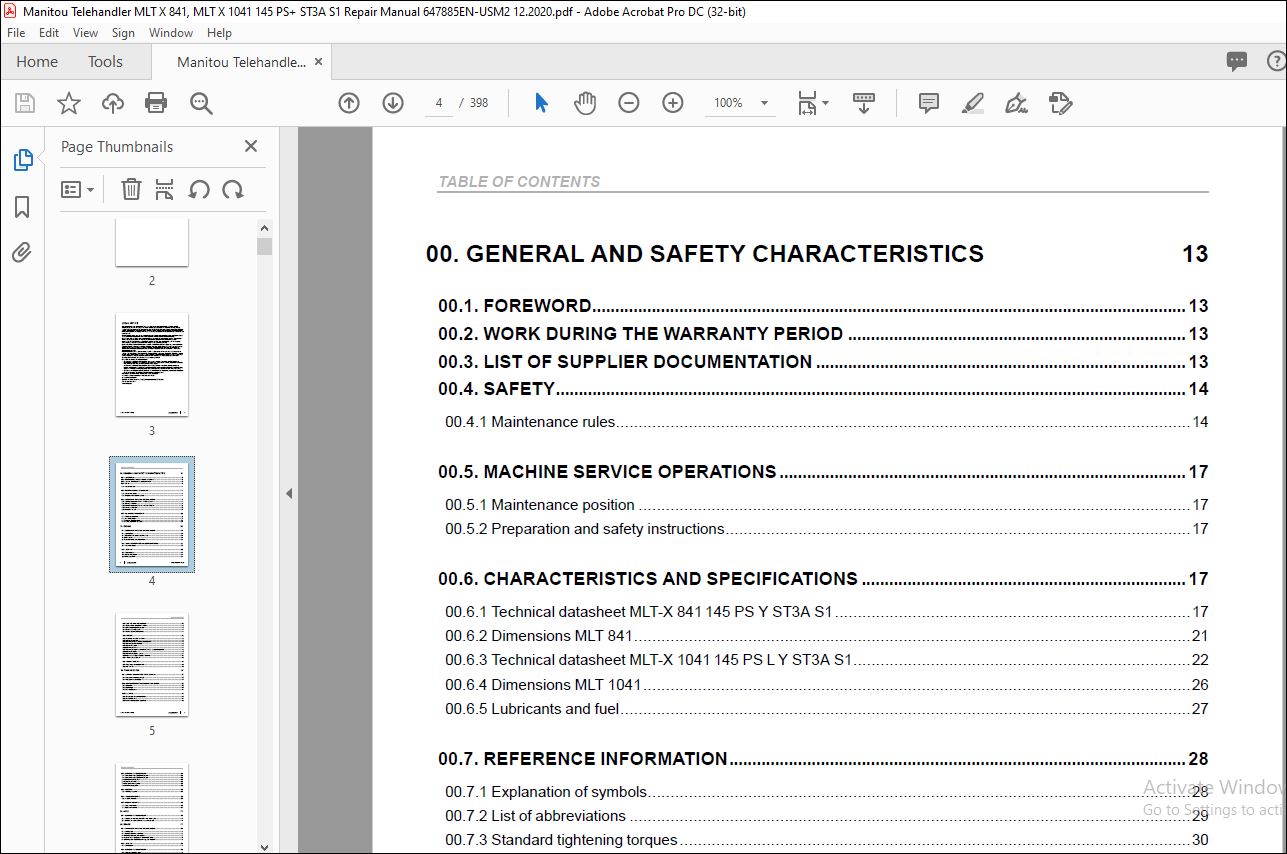
TABLE OF CONTENTS:
Manitou Telehandler MLT—X 841 145 PS+ Y ST3A S1 MLT—X 1041 145 PS+ L Y ST3A S1 Service Manual 647885EN-USM2 – PDF DOWNLOAD
00 GENERAL AND SAFETY CHARACTERISTICS 13
00 1 FOREWORD 13
00 2 WORK DURING THE WARRANTY PERIOD 13
00 3 LIST OF SUPPLIER DOCUMENTATION 13
00 4 SAFETY 14
00 4 1 Maintenance rules 14
00 5 MACHINE SERVICE OPERATIONS 17
00 5 1 Maintenance position 17
00 5 2 Preparation and safety instructions 17
00 6 CHARACTERISTICS AND SPECIFICATIONS 17
00 6 1 Technical datasheet MLT-X 841 145 PS Y ST3A S1 17
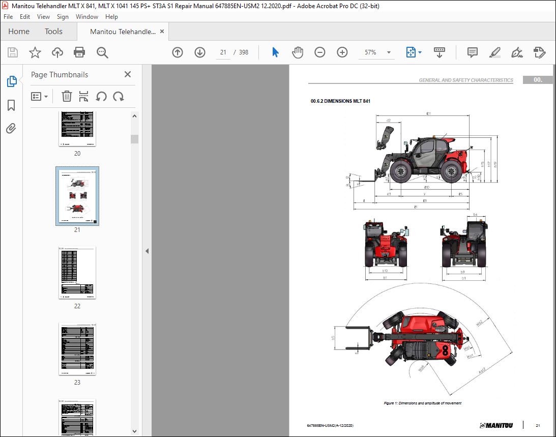
00 6 2 Dimensions MLT 841 21
00 6 3 Technical datasheet MLT-X 1041 145 PS L Y ST3A S1 22
00 6 4 Dimensions MLT 1041 26
00 6 5 Lubricants and fuel 27
00 7 REFERENCE INFORMATION 28
00 7 1 Explanation of symbols 28
00 7 2 List of abbreviations 29
00 7 3 Standard tightening torques 30
00 7 4 Metric – imperial unit conversion 32
10 ENGINE 34
10 1 CHARACTERISTICS AND SPECIFICATIONS 34
10 1 1 Specifications 34
10 1 2 Description of hydraulic motor with control 34
10 1 3 Fan control 34
10 1 4 Conditions of fan control components 35
10 2 FLOW DIAGRAMS AND SCHEMATIC DIAGRAMS 37
10 2 1 Schematic diagram 37
10 3 LOCATION 38
10 3 1 Engine location 38
10 3 2 Water cooling system 39
10 3 3 Diesel fuel circuit 39
4 647885EN-USM2(A-12/2020)
TABLE OF CONTENTS
10 4 CONTROL AND ADJUSTMENT 40
10 4 1 Engine start-up authorization conditions 40
10 4 2 Exhaust circuit tightening torques 40
10 4 3 Engine tightening torques 41
10 4 4 Heating system tightening torque 41
10 5 REMOVAL 42
10 5 1 Preparation and safety instructions 42
10 5 2 Remove the alternator 42
10 5 3 Removing the air conditioning compressor belt 42
10 5 4 Removing the attachment belt 43
10 5 5 Remove the starter 43
10 5 6 Removing the exhaust 44
10 5 7 Removing the engine and removing the engine + gearbox (preparation) 45
10 5 8 Remove the engine 49
10 5 9 Removing the engine + gearbox 51
10 5 10 Disconnect the engine / gearbox / converter 54
10 5 11 Removing the diesel tank 55
10 6 SPECIFIC TOOLING 55
10 6 1 Fitting wedge for elastic drive belt 55
10 6 2 DEF flush kit 56
20 TRANSMISSION 57
20 1 CHARACTERISTICS AND SPECIFICATIONS 57
20 1 1 PS09 gearbox operating principle 57
20 1 2 PS09 gearbox technologies 57
20 2 FLOW DIAGRAMS AND SCHEMATIC DIAGRAMS 59
20 2 1 Drive train 59
20 2 2 Control logic 60
20 2 3 Schematic diagram 61
20 3 LOCATION 63
20 3 1 Pressure port and connector location 63
20 3 2 Transmission circuit 64
20 3 3 Gearbox cooling circuits: hydraulic oil 65
TABLE OF CONTENTS
647885EN-USM2(A-12/2020) 5
20 4 CONTROL AND ADJUSTMENT 66
20 4 1 Transmission assembly tightening torques 66
20 4 2 Transmission assembly tightening torques 66
20 4 3 Bleeding the parking brake 67
20 4 4 Pressure port values 68
20 4 5 Top up the oil in the gearbox 68
20 4 6 Calibrating the gearbox 68
20 5 REMOVAL 68
20 5 1 Removing the gearbox 68
20 6 TROUBLESHOOTING 68
20 6 1 Gearbox error codes 68
20 7 SPECIFIC TOOLING 68
20 7 1 Basic manometer box 68
20 7 2 Digital manometer box 69
30 AXLE 70
30 1 CONTROL AND ADJUSTMENT 70
30 1 1 Adjusting the axle stops, “500/70R24 wide wheels” option 70
30 1 2 Adjusting the mounting of the rear axle on the chassis 72
40 BRAKE 73
40 1 CHARACTERISTICS AND SPECIFICATIONS 73
40 1 1 Parking brake 73
40 1 2 Parking brake release conditions 73
40 1 3 Parking brake application conditions 73
40 1 4 Service brake – Specifications of oil bath disc brakes 74
40 1 5 Parking brake – Specifications of the gearbox disc brake 75
40 2 LOCATION 75
40 2 1 Brake location 75
40 3 CONTROL AND ADJUSTMENT 76
40 3 1 Brake valve tightening torque 76
40 3 2 Adjusting the service brake pedal 76
6 647885EN-USM2(A-12/2020)
TABLE OF CONTENTS
40 3 3 Adjusting the inching potentiometer on the brake pedal 77
40 3 4 Calibrating the inching function 78
40 3 5 Calibrating the inching point 78
40 3 6 Bleeding the braking circuit 78
40 3 7 Bleed the brake accumulators 78
40 3 8 Procedures for adjusting the parking brake 78
40 3 9 Bleeding the parking brake circuit 79
40 3 10 Bleeding the parking brake accumulator 80
40 3 11 Towing procedure 80
40 4 REMOVAL 81
40 4 1 Removing the master cylinder 81
40 5 REFIT 81
40 5 1 Adjusting the brake pedal 81
50 LIFTING STRUCTURE 84
50 1 CHARACTERISTICS AND SPECIFICATIONS 84
50 1 1 Duplex / Triplex Booms 84
50 2 FLOW DIAGRAMS AND SCHEMATIC DIAGRAMS 85
50 2 1 Duplex boom kinematics 87
50 2 2 Triplex boom kinematics 89
50 3 LOCATION 91
50 3 1 Index of component codes 91
50 4 CONTROL AND ADJUSTMENT 92
50 4 1 Telescope retraction and extension time adjustment procedure 92
50 4 2 Tightening torque and lubrication Duplex boom 93
50 4 3 Tightening torque and lubrication Triplex boom 95
50 4 4 Shim installation and greasing area instructions Duplex boom 97
50 4 5 Shim installation and greasing area instructions Triplex boom 101
50 4 6 Slide pad mounting instructions Triplex boom 103
50 5 REMOVAL 105
50 5 1 Removal of Duplex boom internal components 105
50 5 2 Removing the Duplex boom telescope circuit 105
50 5 3 Removal of Triplex boom internal components 112
TABLE OF CONTENTS
647885EN-USM2(A-12/2020) 7
50 5 4 Remove the Triplex boom telescope circuit 113
50 5 5 Removing the T1 telescope Duplex boom 117
50 5 6 Removing the T1 and T2 telescopes Triplex boom 119
50 5 7 Preparation for Duplex boom removal 120
50 5 8 Removing the Duplex boom 121
50 5 9 Preparation for Triplex boom removal 125
50 5 10 Removing the Triplex boom 125
50 6 REFIT 131
50 6 1 Refitting Duplex boom components 131
50 6 2 Refitting the Duplex boom telescope circuit 131
50 6 3 Refitting Triplex boom components 136
50 6 4 Refitting the Triplex boom telescope circuit 136
50 6 5 Refitting the Duplex boom telescope 141
50 6 6 Refitting the T1 and T2 telescopes Triplex boom 144
50 6 7 Refitting the intermediate telescope T1 Triplex boom 145
50 6 8 Refitting the boom head telescope T2, Triplex boom 151
50 6 9 Preparation for Duplex boom refit 153
50 6 10 Refitting the Duplex boom 154
50 6 11 Preparation for Triplex boom refit 157
50 6 12 Refitting the Triplex boom 157
50 7 SPECIFIC TOOLING 162
50 7 1 Pipe end pieces 162
50 7 2 Magnetic lifter 162
70 HYDRAULICS 164
70 1 CHARACTERISTICS AND SPECIFICATIONS 164
70 1 1 Feed block + accumulator 164
70 1 2 OSPEDF 125/250 LS steering pump 166
70 1 3 Fan control hydraulic motor (control and reversal) 169
70 1 4 Brake valve 173
70 1 5 trailer brake valve 177
70 1 6 Compensating isolation valve (VIC) 180
70 1 7 Boom suspension electrovalve 181
70 1 8 Boom suspension electrovalve 181
70 1 9 Boom suspension electrovalve with or without regeneration (option) 182
70 2 FLOW DIAGRAMS AND SCHEMATIC DIAGRAMS 183
70 2 1 Hydraulic diagram 185
8 647885EN-USM2(A-12/2020)
TABLE OF CONTENTS
70 3 LOCATION 191
70 3 1 Location of hydraulic components MLT 841 193
70 3 2 Location of hydraulic components MLT 1041 195
70 4 CONTROL AND ADJUSTMENT 197
70 4 1 Hydraulic pump tightening torques 197
70 4 2 Accumulator block tightening torque 198
70 4 3 Distributor tightening torque 199
70 4 4 Boom suspension option 199
70 5 REMOVAL 201
70 5 1 Preparation and safety instructions 201
70 5 2 Removing the fan motor 201
70 5 3 Removing the engine fan and the radiator 202
70 5 4 Removing the main distributor 206
70 5 5 Remove the hydraulic pump 207
70 5 6 Removing the hydraulic oil and diesel tanks 209
70 5 7 Remove the compensating cylinder 215
70 5 8 Remove the lifting cylinder 217
70 5 9 Remove the leveling cylinder 219
70 6 REFIT 221
70 6 1 Refit the lifting cylinder 221
70 7 SPECIFIC TOOLING 221
70 7 1 Strainer socket wrench 221
70 7 2 Digital manometer box 222
70 7 3 Basic manometer box 222
80 ELECTRICITY 223
80 1 CHARACTERISTICS AND SPECIFICATIONS 223
80 1 1 X13 (1) X25 (2) – Screen (A9) 223
80 1 2 X14 – Navigator (A4) 224
80 1 3 X80 / X81 / X82- Main ECU SPU 40-26 (A2) 225
80 1 4 X356 / X357 AUXILIARY ECU SPU 25-15 (A3) 228
80 1 5 X323 / X324 TRANSMISSION ECU APC312 SPU 28-16 (A10) 230
80 1 6 X274 / X275 – ENGINE ECU (A19) 233
80 1 7 Ignition and starter switch 235
80 1 8 Rotating beacon light 236
80 1 9 Wiper stalk 236
TABLE OF CONTENTS
647885EN-USM2(A-12/2020) 9
80 1 10 Lighting stalk 237
80 1 11 Reversing alarm 238
80 1 12 Front horn 238
80 1 13 Brake pedal angular sensor 239
80 1 14 Accelerator pedal angular sensor 239
80 2 FLOW DIAGRAMS AND SCHEMATIC DIAGRAMS 240
80 2 1 Examples of coding on the wiring diagrams 240
80 2 2 Cable marking on an electrical wiring harness 241
80 2 3 Electrical diagrams by function 243
80 3 LOCATION 265
80 3 1 3D and 2D Location 267
80 4 CONTROL AND ADJUSTMENT 279
80 4 1 Adjust the boom angular sensor 279
80 5 REMOVAL 279
80 5 1 Remove the dashboard screen 279
80 5 2 Remove the main ECU “SPU 40-26” 280
80 5 3 Removing the engine ECU 281
80 5 4 Remove the gearbox ECU 281
80 5 5 Remove the auxiliary ECU 282
80 5 6 Removing the strain gage 282
80 6 REFIT 283
80 6 1 Refit the JSM on BMEP 283
80 6 2 Refitting the strain gage 283
80 7 TROUBLESHOOTING 286
80 7 1 DTC ECU Harmony screen 286
80 7 2 DTC Main ECU (SPU 40-26) 287
80 7 3 DTC engine ECU (Yanmar 4TN107FHT-5SMUF) 296
80 7 4 DTC gear box ECU PS09 SAE3 (SPU 28–16–3 STD2) 301
80 7 5 DTC auxiliary ECU (SPU 25-15-STD2) or (SPU 40-26 PWM) 338
80 7 6 Automatic air conditioning error codes 344
80 8 SPECIFIC TOOLING 345
80 8 1 Electrovalve adapter 345
80 8 2 Breakout boxes 345
10 647885EN-USM2(A-12/2020)
TABLE OF CONTENTS
85 OPERATOR STATION 346
85 1 CHARACTERISTICS AND SPECIFICATIONS 346
85 1 1 Description of air conditioning operation 346
85 1 2 Automatic air conditioning ECU inputs/outputs 346
85 1 3 Evaporator temperature sensor specifications 347
85 2 FLOW DIAGRAMS AND SCHEMATIC DIAGRAMS 349
85 2 1 Schematic diagrams 349
85 3 LOCATION 351
85 3 1 HVAC components 351
85 3 2 Automatic air conditioning location 353
85 3 3 Condenser component 354
85 4 CONTROL AND ADJUSTMENT 354
85 4 1 General checkpoints 354
85 4 2 Air conditioning assembly instructions 355
85 4 3 Safety measures for handling R134a 355
85 4 4 Check the evaporator temperature sensor 355
85 4 5 Refrigerant fluid charging 357
85 4 6 Cab air conditioning tightening torques 358
85 4 7 Cab suspension silent block tightening torques 359
85 4 8 Windshield grille tightening torques 359
85 4 9 Windshield wiper motor tightening torques 360
85 5 REMOVAL 360
85 5 1 Removing the cab 360
85 5 2 Removing the windshield with standard grille 365
85 5 3 Remove the rear cab casing 366
85 5 4 Removing the cab lower trim 366
85 5 5 Remove the cab seat 367
85 5 6 Removing the cab heating and air conditioning unit 368
85 5 7 Removing the condenser 370
85 5 8 Remove the cab door 371
85 5 9 Removing the door window winder 371
85 6 REFIT 375
85 6 1 Removing the door window winder 375
TABLE OF CONTENTS
647885EN-USM2(A-12/2020) 11
85 7 TROUBLESHOOTING 378
85 7 1 Temperature fault 378
85 7 2 Unusual noise 379
85 7 3 Unpleasant smell 379
85 7 4 Automatic air conditioning error codes 379
85 8 SPECIFIC TOOLING 379
85 8 1 Cab grille hinge kit 379
90 CHASSIS 381
90 1 REMOVAL 381
90 1 1 Remove the engine hood 381
90 1 2 Removing the engine housing 381
110 ADDITIONAL EQUIPMENT 383
110 1 AIR CONDITIONING 383
110 1 1 Air conditioning 383
110 2 AUTOMATIC CENTRAL GREASING 383
110 2 1 Automatic greasing characteristics and specifications 383
110 2 2 Schematic diagram of the distributors 387
110 2 3 Location of automatic central greasing 388
110 2 4 Automatic central greasing controls and adjustments 389
110 2 5 Tightening torques of automatic central greasing connections 390
110 2 6 Troubleshooting 390
110 2 7 Error codes table 393
120 DIAGNOSTIC TOOLS AND SOFTWARE 395
120 1 ELECTRONIC BELT TENSIOMETER 395
120 2 SMARTASSIST-DIRECT DIAGNOSTICS AND CONTROL TOOL 395
120 3 DIAGNOSTICS CASE 395
120 4 COMPONENT DIAGNOSTICS BOX 397
VIDEO PREVIEW OF THE MANUAL:
PLEASE NOTE:
- This is the same manual used by the DEALERSHIPS to SERVICE your vehicle.
- The manual can be all yours – Once payment is complete, you will be taken to the download page from where you can download the manual. All in 2-5 minutes time!!
- Need any other service / repair / parts manual, please feel free to contact us at heydownloadss @gmail.com . We may surprise you with a nice offer
S.V


