Mack Truck ASET™ AC DIESEL ENGINE SERVICE MANUAL(5-111) – PDF DOWNLOAD
FILE DETAILS:
Mack Truck ASET™ AC DIESEL ENGINE SERVICE MANUAL(5-111) – PDF DOWNLOAD
Language : English
Pages : 536
Downloadable : Yes
File Type : PDF
Size: 47.5 MB
DESCRIPTION:
Mack Truck ASET™ AC DIESEL ENGINE SERVICE MANUAL(5-111) – PDF DOWNLOAD
INTRODUCTION
Mack Trucks, Inc. cannot anticipate every possible occurrence that may involve a potential hazard. Accidents can be avoided by recognizing potentially hazardous situations and taking necessary precautions. Performing service procedures correctly is critical to technician safety and safe, reliable vehicle operation.
The following list of general shop safety practices can help technicians avoid potentially hazardous situations and reduce the risk of personal injury. DO NOT perform any services, maintenance procedures or lubrications until this manual has been read and understood.
- Perform all service work on a flat, level surface. Block wheels to prevent vehicle from rolling.
- DO NOT wear loose-fitting or torn clothing. Remove any jewelry before servicing vehicle.
- ALWAYS wear safety glasses and protective shoes. Avoid injury by being aware of sharp corners and jagged edges.
- Use hoists or jacks to lift or move heavy objects.
- NEVER run engine indoors unless exhaust fumes are adequately vented to the outside.
- Be aware of hot surfaces. Allow engine to cool sufficiently before performing any service or tests in the vicinity of the engine.
- Keep work area clean and orderly. Clean up any spilled oil, grease, fuel, hydraulic fluid, etc.
- Only use tools that are in good condition, and always use accurately calibrated torque wrenches to tighten all fasteners to specified torques. In instances where procedures require the use of special tools which are designed for a specific purpose, use only in the manner described in the instructions.
- Do not store natural gas powered vehicles indoors for an extended period of time (overnight) without first removing the fuel.
- Never smoke around a natural gas powered vehicle.
IMAGES PREVIEW OF THE MANUAL:
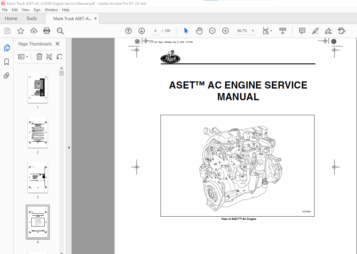
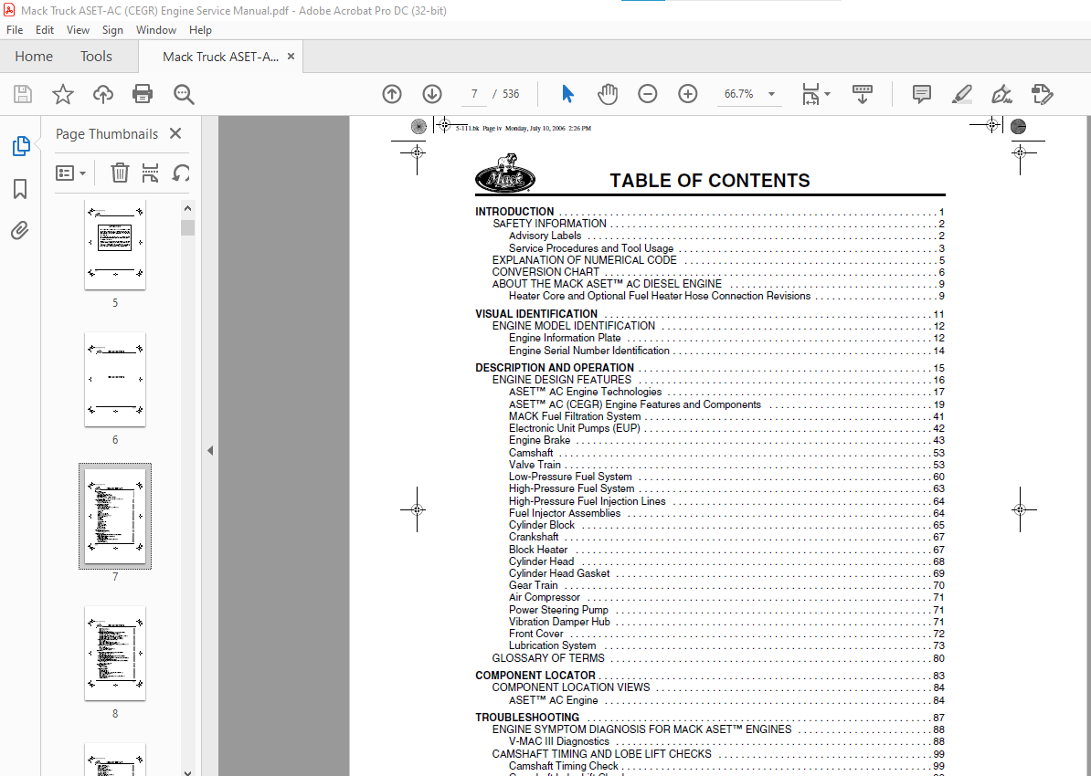
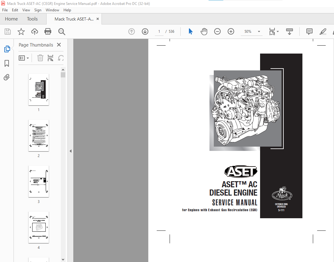
TABLE OF CONTENTS:
Mack Truck ASET™ AC DIESEL ENGINE SERVICE MANUAL(5-111) – PDF DOWNLOAD
INTRODUCTION 1
SAFETY INFORMATION 2
Advisory Labels 2
Service Procedures and Tool Usage 3
EXPLANATION OF NUMERICAL CODE 5
CONVERSION CHART 6
ABOUT THE MACK ASET™ AC DIESEL ENGINE 9
Heater Core and Optional Fuel Heater Hose Connection Revisions 9
VISUAL IDENTIFICATION 11
ENGINE MODEL IDENTIFICATION 12
Engine Information Plate 12
Engine Serial Number Identification 14
DESCRIPTION AND OPERATION 15
ENGINE DESIGN FEATURES 16
ASET™ AC Engine Technologies 17
ASET™ AC (CEGR) Engine Features and Components 19
MACK Fuel Filtration System 41
Electronic Unit Pumps (EUP) 42
Engine Brake 43
Camshaft 53
Valve Train 53
Low-Pressure Fuel System 60
High-Pressure Fuel System 63
High-Pressure Fuel Injection Lines 64
Fuel Injector Assemblies 64
Cylinder Block 65
Crankshaft 67
Block Heater 67
Cylinder Head 68
Cylinder Head Gasket 69
Gear Train 70
Air Compressor 71
Power Steering Pump 71
Vibration Damper Hub 71
Front Cover 72
Lubrication System 73
GLOSSARY OF TERMS 80
COMPONENT LOCATOR 83
COMPONENT LOCATION VIEWS 84
ASET™ AC Engine 84
TROUBLESHOOTING 87
ENGINE SYMPTOM DIAGNOSIS FOR MACK ASET™ ENGINES 88
V-MAC III Diagnostics 88
CAMSHAFT TIMING AND LOBE LIFT CHECKS 99
Camshaft Timing Check 99
Camshaft Lobe Lift Check 99
CHASSIS-MOUNTED CHARGE AIR COOLING TESTS 100
General Information 100
Special Tool Required 100
CMCAC Troubleshooting 100
5-111bk Page iv Monday, July 10, 2006 2:26 PM
TABLE OF CONTENTS
Page v
CMCAC Pressure Test 101
Restriction Pressure Test 102
Core Inspection 103
CMCAC Preventive Maintenance 103
CYLINDER HEAD AND CYLINDER BLOCK LEAK TEST PROCEDURE 104
Cylinder Head and Head Gasket Check — In Chassis 104
Cylinder Head Fuel Passages Leak Check — In Chassis 105
Cylinder Block/Cylinder Head Coolant Passages Leak Check — In Chassis 105
Cylinder Head Oil Passage Leak Check — Out of Chassis 107
Cylinder Head Coolant Passage Leak Check — Out of Chassis 108
Cylinder Block Coolant Passage Leak Check — Out of Chassis 109
ENGINE BRAKE TESTS (MACK POWERLEASH™) 111
Operational Tests 111
Electrical Troubleshooting 112
MACK PowerLeash™ Checks (Hydraulic/Mechanical) 113
MACK PowerLeash™ Troubleshooting Guide 115
Removal and Inspection of MACK PowerLeash™ Engine Brake Components 117
ENGINE BRAKE TESTS (J-TECH™) 119
Operational Tests 119
Electrical Troubleshooting 120
J-Tech™ Checks (Hydraulic/Mechanical) 121
J-Tech™ Troubleshooting Guide 124
MAINTENANCE 127
LUBRICATION SYSTEM MAINTENANCE FOR ASET™ ENGINES 128
Crankcase Breather Element Cleaning 128
Oil Level Check 129
Oil and Filter Change Procedure 130
FUEL FILTER ELEMENT REPLACEMENT FOR ASET™ AC ENGINES 134
Primary/Secondary Fuel Filter Change 134
COOLANT CONDITIONER ELEMENT REPLACEMENT FOR ASET™ ENGINES 137
Coolant Conditioner Replacement 137
OIL COALESCING AIR FILTER REPLACEMENT 137
DRIVE BELT REPLACEMENT AND TENSIONING FOR ASET™ AC ENGINES 138
General Information 138
Automatically Tensioned System 139
REPAIR INSTRUCTIONS, PART 1 141
ENGINE REMOVAL 142
General Instructions 142
Removal from Vehicle 142
ENGINE DISASSEMBLY 145
General Instructions 145
Filter Element Removal 145
Dipstick Tube Removal 146
Oil Cooler and Oil Filter Mounting Bracket Assembly Removal 146
Oil Coalescing Air Filter Removal 147
Mounting Engine in Stand 148
Alternator Removal 150
Engine Electronic Control Unit (EECU) and Cooling Plate Removal 150
EGR Gas Tube Removal 152
EGR Cooler Removal 154
5-111bk Page v Monday, July 10, 2006 2:26 PM
Page vi
TABLE OF CONTENTS
EGR Mixer Tube Removal 155
Thermostat Housing Removal 156
Oil Supply Lines Removal 157
EGR Valve Removal 159
Water Pump Housing Removal 160
VTG Position Control Valve Removal 162
Coolant Manifold Removal 163
Air Inlet Manifold Removal 163
Turbocharger Removal 163
Fuel Nozzle Inlet Tube Assembly Removal 164
Exhaust Manifold Removal 165
Engine Wiring Harness Removal 165
Electronic Unit Pump (EUP) Removal 166
Air Compressor Removal 167
Cylinder Head Cover and Spacer Removal 169
Rocker Arm, Valve Yoke and Push Rod Removal 170
Revised Rocker Arm Shift Mounting Bolts 172
Nozzle Holder Removal 173
Cylinder Head Assembly Removal 173
Vibration Damper and Crankshaft Hub Removal 175
Oil Pan Removal 175
Oil Pump Removal 177
Front Cover Removal 178
Auxiliary Shaft Removal 178
Camshaft Removal 179
Piston and Connecting Rod Assembly Removal 180
Flywheel Removal 182
Flywheel Housing Removal 183
Main Bearing Cap Removal 183
Crankshaft Removal 185
CYLINDER BLOCK RECONDITIONING 185
Special Tools Required 185
Piston Cooling Spray Nozzle Removal 185
Cylinder Sleeve Removal 186
Cleaning and Inspection 187
Cylinder Sleeve Counterbore 190
Cup Plug Replacement 194
Pipe Plug Replacement 194
H-Ring Replacement 195
Camshaft Bushing Replacement 197
Auxiliary Shaft Bushing Replacement 201
Cylinder Sleeve Installation 205
Piston Cooling Spray Nozzle Installation 208
Cylinder Block Dowel Pin Replacement 211
CRANKSHAFT AND FLYWHEEL BENCH PROCEDURES 213
General Information 213
Crankshaft Inspection 213
Crankshaft Dowel Pin Replacement 213
Crankshaft Gear Replacement 214
Crankshaft Wear Ring Installation 215
Flywheel Inspection and Resurfacing 217
5-111bk Page vi Monday, July 10, 2006 2:26 PM
TABLE OF CONTENTS
Page vii
AUXILIARY SHAFT AND CAMSHAFT BENCH PROCEDURES 219
Auxiliary Shaft Inspection 219
Camshaft Inspection 219
CONNECTING ROD AND PISTON BENCH PROCEDURES 223
Connecting Rod Inspection and Reconditioning 223
Piston Inspection and Cleaning 226
Piston Ring Replacement 226
Assembling Connecting Rod to Piston 229
CYLINDER HEAD OVERHAUL 230
Special Tools Required 230
Inlet and Exhaust Valve Removal 230
Cylinder Head Cleaning and Inspection 234
Fire Ring Groove Cutting 235
Valve Guide Replacement 238
Valve Seat Insert Replacement 241
Valve Spring Inspection 247
Injection Nozzle Holder Insert Replacement 248
Valve Yoke Guide Pin Replacement 250
Cylinder Head Cup Plug Replacement 251
Cylinder Head Pipe Plug Replacement 252
Inlet and Exhaust Valve Inspection 253
Inlet and Exhaust Valve Installation 254
VALVE ROCKER ARM SHAFT BENCH PROCEDURES 260
Rocker Arms 260
Valve Rocker Arm Shaft Disassembly (with/without Engine Brake) 262
Inspection 263
Valve Rocker Arm Shaft Reassembly (without Engine Brake) 264
Valve Rocker Arm Shaft Reassembly (with J-Tech™ Engine Brake) 266
Valve Rocker Arm Shaft Reassembly (with MACK PowerLeash™ Engine Brake) 268
LUBRICATION SYSTEM BENCH PROCEDURES 273
Oil Cooler Assembly Reconditioning 273
Oil Pump Reconditioning 273
COOLING SYSTEM COMPONENTS BENCH PROCEDURES 279
Oil Cooler Reconditioning 279
EGR Cooler Reconditioning 279
Water Pump Reconditioning 279
FUEL SYSTEM COMPONENT BENCH PROCEDURES 280
Electronic Unit Pump (EUP) Inspection 280
Installation of Electronic Unit Pump Plunger Spring and Seat 280
Fuel Injector Nozzle Cleaning 283
VTG SYSTEM BENCH PROCEDURES 284
VTG Control Valve Solenoid Replacement 284
ENGINE REASSEMBLY 286
General Instructions 286
Crankshaft Installation 286
Main Bearing Cap Installation 287
Piston and Connecting Rod Installation 293
Flywheel Housing Installation 298
Crankshaft Rear Oil Seal Installation 301
Flywheel Installation 304
Valve Lifter Installation 305
5-111bk Page vii Monday, July 10, 2006 2:26 PM
Page viii
TABLE OF CONTENTS
Camshaft Installation 307
Camshaft Core Plug Installation 308
Camshaft Idler Gear Installation 308
Auxiliary Shaft Installation 309
Oil Pump Installation 310
Front Cover Installation 311
Crankshaft Front Seal Installation 312
Crankshaft Hub Installation 313
Vibration Damper Installation 313
Oil Pan Installation 314
Cylinder Head Installation 316
Exhaust Manifold Installation 319
Nozzle Holder Assembly Installation 320
Push Rod Installation 323
Valve Yoke Installation 324
Rocker Arm and Engine Brake Installation 328
Cylinder Head Cover and Spacer Installation 334
Oil Fill Tube/Dipstick Installation 336
Air Compressor Installation 336
Electronic Unit Pump (EUP) Installation 338
Engine Wiring Harness Installation 339
Fuel Nozzle Inlet Tube Assembly Installation 339
Turbocharger Installation 342
Coolant Manifold Installation 343
Air Inlet Manifold Installation 344
VTG Position Control Valve Installation 344
Water Pump Housing Installation 345
EGR Valve Installation 348
Oil Supply Lines Installation 350
Thermostat Housing Installation 353
EGR Mixer Tube Installation 356
EGR Cooler Installation 357
EGR Gas Tube Installation 358
EECU and Cooling Plate Installation 360
Coolant Conditioner Installation 362
Alternator Installation 363
Removing Engine from Engine Stand 363
Oil Coalescing Air Filter Installation 364
Oil Cooler and Oil Filter Mounting Bracket Assembly Installation 364
Dipstick Tube Installation 366
ENGINE INSTALLATION 366
General Instructions 366
Engine Installation into Vehicle 366
REPAIR INSTRUCTIONS, PART 2 371
IN-CHASSIS PART/COMPONENT PROCEDURES 372
ELECTRONIC UNIT PUMP REPLACEMENT (IN-CHASSIS) 372
Unit Pump Removal 372
Tappet Guide Pin and Tappet Bore Inspection 373
Salvaging a Damaged EUP Tappet Bore 373
Tappet Installation 374
Unit Pump Installation 374
5-111bk Page viii Monday, July 10, 2006 2:26 PM
TABLE OF CONTENTS
Page ix
CAMSHAFT REPLACEMENT (IN-CHASSIS) 376
Preliminary Steps 376
Camshaft/Lifter Removal 376
Cleaning and Inspection of Cylinder Block 378
Camshaft Installation 379
Camshaft Idler Gear Installation 380
EXHAUST VALVE YOKE PIN AND VALVE ROTATOR INSPECTION AND REPLACEMENT
CRITERIA (IN-CHASSIS) 382
VALVE LIFTER H-RING DISLODGEMENT AND ALIGNMENT INSPECTIONS
(IN-CHASSIS) 384
H-Ring Dislodgement Inspection 385
H-Ring Alignment Inspection 385
H-Ring Dislodgement Check and Alignment Verification 386
EECU AND SENSOR SERVICE PROCEDURES (IN-CHASSIS) 387
Engine Electronic Control Unit (EECU) and Cooling Plate Removal 387
EECU and Cooling Plate Installation 389
Sensors Installation and Adjustment 390
COOLING SYSTEM SERVICE PROCEDURES (IN-CHASSIS) 391
Thermostat Replacement 391
Water Pump Housing Assembly Removal and Installation 396
Coolant Conditioner Adapter Removal and Installation 401
EGR SYSTEM SERVICE PROCEDURES (IN-CHASSIS) FOR ASET™ AC ENGINE 402
Preliminary Steps 402
EGR Gas Tube(s) Removal and Installation 402
EGR Cooler Removal and Installation 408
EGR Valve Removal and Installation 412
EGR Valve Heat Shields Removal and Installation 416
EGR Gas Mixer Tube Removal and Installation 417
MASS Flow System Replacement Instructions 420
Final Assembly 421
VTG TURBOCHARGER SERVICE PROCEDURES 422
Preliminary Steps 422
VTG Position Control Valve Removal and Installation 422
Turbocharger Removal 424
Turbocharger Installation (Includes Pre-Lubing Procedures) 426
VTG Actuator Removal and Installation 428
VTG Actuating System Calibration 435
Turbocharger Wheel Speed Sensor Replacement 439
REPAIR INSTRUCTIONS, PART 3 441
ENGINE SETUP AND ADJUSTMENTS 442
Fuel Injection Timing 442
Valve Adjustment 442
Valve Adjustment Procedure 443
Electronic Unit Pump (EUP) Calibration 460
ENGINE SPEED AND POSITION SENSORS INSTALLATION AND ADJUSTMENT 460
Engine Speed Sensor 460
Engine Position Sensor 461
Other Engine-Mounted Sensors 461
5-111bk Page ix Monday, July 10, 2006 2:26 PM
Page x
TABLE OF CONTENTS
ENGINE FINAL PREPARATION AND OPERATIONAL CHECK 462
Filter Element Installation 462
Engine Lubrication System 462
Turbocharger 463
Cooling System 463
Fuel System 464
Engine Operational Check 465
REBUILT ENGINE RUN-IN PROCEDURES 465
General Instructions 465
Run-In Check 465
SPECIFICATIONS 467
ASET™ AC ENGINE MECHANICAL SPECIFICATIONS 468
Performance Specifications 468
Material and Dimensional Data 469
Engine Component Torque Specifications 478
SPECIFICATION FOOTNOTES 488
ASET™ ENGINE ASSEMBLY LUBRICANTS AND SEALANTS 490
ASET™ AC ENGINE DRIVE BELT SPECIFICATIONS 491
SCHEMATIC & ROUTING DIAGRAMS 493
ASET™ AC ENGINE SYSTEMS SCHEMATICS 494
Cooling System Flow Diagrams 494
Lubrication System Flow Diagrams 495
Fuel System Flow Diagrams 496
Accessory Drive Belt Routings 499
SPECIAL TOOLS & EQUIPMENT 501
ASET™ ENGINE SPECIAL TOOLS 502
Special Tools for Engine Overhaul 502
V-MAC III Special Tools 505
APPENDIX 507
FASTENER IDENTIFICATION 508
Fastener Selection and Installation 508
Fastener Sizes and Types 509
TORQUE WRENCH USE 510
Using an Adapter in Combination with a Torque Wrench 510
TURBOCHARGER FAILURE AND ACTIONS REQUIRED TO AVOID REPEAT FAILURE 511
Cleaning Oil from the Charge Air Cooler 512
Cleaning the Intake Air System 512
Cleaning the Turbocharger Oil Supply Line, Changing the Engine Oil and Pre-Lubricating
the Turbocharger Following a Failure 513
Pre-Lubricating a Turbocharger After Sitting Idle for an Extended Period of Time 514
INDEX 515
VIDEO PREVIEW OF THE MANUAL:
PLEASE NOTE:
- This is the SAME manual used by the dealers to troubleshoot any faults in your vehicle. This can be yours in 2 minutes after the payment is made.
- Contact us at [email protected] should you have any queries before your purchase or that you need any other service / repair / parts operators manual.
S.M