

Linkbelt 240LX EXCAVATOR SHOP MANUAL 1033 – PDF DOWNLOAD
IMAGES PREVIEW OF THE MANUAL:
DESCRIPTION:
Linkbelt 240LX EXCAVATOR SHOP MANUAL 1033 – PDF DOWNLOAD
Cleaning:
Clean all metal parts except bearings, in a suitable cleaning solvent or by steam cleaning. Do not use caustic soda for steam cleaning. After cleaning, dry and put oil on all parts. Clean oil passages with compressed air. Clean bearings in a suitable cleaning solvent. Dry the bearings completely and put oil on the bearings.
Inspection:
Check all parts when the parts are disassembled. Replace all parts that have wear or damage. Small scoring or grooves can be removed with a hone or crocus cloth. Complete a visual inspection for indications of wear, pitting and the replacement of parts necessary to prevent early failures.
Bearings:
Check bearings for easy action. If bearings have a loose fit or rough action, replace the bearing. Wash bearings with a suitable cleaning solvent and permit to air dry. DO NOT DRY BEARINGS WITH COMPRESSED AIR.
Needle Bearings:
.Before you press needle bearings in a bore always remove any metal protrusions in the bore or edge of the bore. Before you press bearings into position, put petroleum jelly on the inside and outside diameter of the bearings
Gears:
Check all gears for wear and damage. Replace gears that have wear or damage.
Oil Seals, O-rings and Gasket:
Always install new oil seals, O-rings and gaskets. Put petroleum jelly on seals and O-rings
Shafts:
Check all shafts that have wear or damage. Check the bearing and oil seal surfaces of the shafts for damage.
Service Parts:
Always install genuine Link-Belt service parts. When ordering refer to the Parts Catalog for the correct part number of the genuine Link-Belt replacement items. Failures due to the use of other than genuine Link- Belt replacement parts are not covered by warranty.
Lubrication:
Only use the oils and lubricants specified in the Operator’s or Service Manuals. Failures due to the use of non-specified oils and lubricants are not covered by warranty.
TABLE OF CONTENTS:
Linkbelt 240LX EXCAVATOR SHOP MANUAL 1033 – PDF DOWNLOAD
1 GENERAL INFORMATION
Safety, general information and standard torque data 1001 7-27690LX
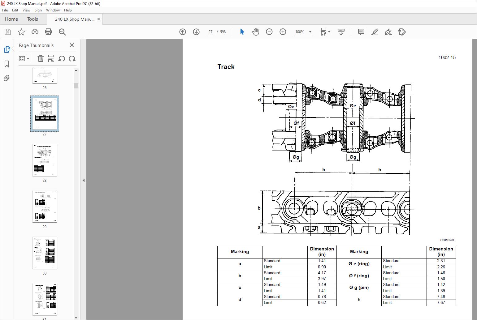
General specifications and special torque setting1002 7-29360-24LX
2 ENGINE
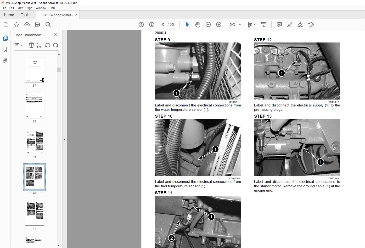
Removal and installation of the engine 2000 7-28230LX
Radiator and oil-cooler2001 7-28050LX
3 FUEL SYSTEM
Removal and installation of the fuel tank 3001 7-27970LX
4 ELECTRICAL SYSTEM
Electrical system, electrical and electronic troubleshooting4001 7-28250-24LX
Inspection and maintenance of batteries and connecting a booster battery4002 7-27921LX
Main and engine electronic control boxes4003 7-27931-24LX
5 UNDERCARRIAGE
Removal and installation of the tracks set 5001 7-27750LX
Upper and lower rollers5003 7-27770-24LX
Sprocket5004 7-27781LX
Idler wheel and tension shock absorber 5005 7-27801-24LX
6 DRIVE TRAIN
Drive motor and final drive transmission removal and installation 6001 7-27841LX
Drive motor and final drive transmission disassembly and assembly 6002 7-28090LX
Swing reduction gear, removal and installation6003 7-27820LX
Swing reduction gear, disassembly and assembly 6004 7-28390LX
7 UNDERCARRIAGE HYDRAULICS
8 UPPERSTRUCTURE HYDRAULICS
Depressurising and decontaminating the hydraulic system, use of the
vacuum pump and bleeding the components 8000 7-27951-24LX
Specifications, troubleshooting, checks and hydraulic pressure settings 8001 7-28270-24LX
Hydraulic sump tank removal and installation8002 7-27990LX
Main and pilot pumps, removal and installation 8003 7-27860LX
Main hydraulic control valve, removal and installation8004 7-27890LX
Attachment cylinders, removal and installation8005 7-27791LX
Rotating joint, removal and installation 8006 7-27811LX
Pilot blocs, removal and installation8007 9-35590LX
Swing motor, removal and installation 8008 7-28070LX
Free swing disassembly and assembly 8009 9-35530LX
Main hydraulic pump, disassembly and assembly8010 7-35490LX
Main hydraulic control valve, disassembly and assembly8011 9-36270LX
Attachment cylinders, disassembly and assembly8012 7-27900-24LX
Hand joystick control, disassembly and assembly8013 7-28110LX
Foot joystick control, disassembly and assembly 8014 7-28210LX
Six stack solenoid valve, disassembly and assembly8015 7-27910LX
Cushion control, disassembly and assembly 8016 7-27940LX
Hose burst check valve8017 7-29630-24LX
Rotating joint, disassembly and assembly 8018 7-28080LX
Swing motor, disassembly and assembly 8019 7-29760LX
Hydraulic functions8020 7-28420-24LX
Cre 7-29880LX Issued 11-01
DIVISION/SECTION SECTION N° REFERENCE N°
9 UPPERSTRUCTURE
Upperstructure, turntable and counterweight9002 7-27981-24LX
Boom, dipper and bucket 9003 7-27961-24LX
Seat and safety belt 9004 7-28120LX
Cab and cab equipment9005 7-28021-24LX
Air conditioning troubleshooting9006
Air conditioning unit disassembly and assembly9007 7-29910GB
Air conditioning servicing 9008
Air conditioning components9009
Large format hydraulic and electrical schematics Pocket 7-28521
VIDEO PREVIEW OF THE MANUAL:
PLEASE NOTE:
- This is the SAME exact manual used by your dealers to fix your vehicle.
- The same can be yours in the next 2-3 mins as you will be directed to the download page immediately after paying for the manual.
- Any queries / doubts regarding your purchase, please feel free to contact [email protected]
I.G


