

Linkbelt 130LX Crawler Excavators Service Manual 1030 – PDF DOWNLOAD
DESCRIPTION:
Linkbelt 130LX Crawler Excavators Service Manual 1030 – PDF DOWNLOAD
TABLE OF CONTENTS:
Linkbelt 130LX Crawler Excavators Service Manual 1030 – PDF DOWNLOAD
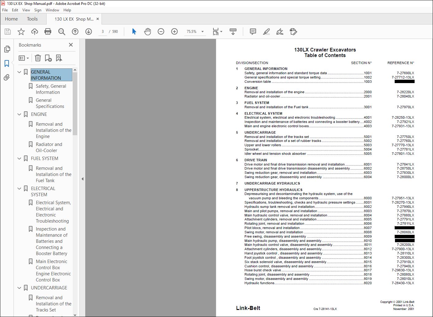
1 GENERAL INFORMATION
Safety, general information and standard torque data 1001 7-27690LX
General specifications and special torque setting 1002 7-27712-13LX
Conversion table 1003 9-35540LX
2 ENGINE
Removal and installation of the engine 2000 7-28220LX
Radiator and oil-cooler 2001 7-28040LX
3 FUEL SYSTEM
Removal and installation of the Fuel tank 3001 7-27970LX
4 ELECTRICAL SYSTEM
Electrical system, electrical and electronic troubleshooting 4001 7-28250-13LX
Inspection and maintenance of batteries and connecting a booster battery 4002 7-27921LX
Main and engine electronic control boxes 4003 7-27931-13LX
5 UNDERCARRIAGE
Removal and installation of the tracks set 5001 7-27750LX
Removal and installation of a set of rubber tracks 5002 7-27760LX
Upper and lower rollers 5003 7-27770-13LX
Sprocket 5004 7-27781LX
Idler wheel and tension shock absorber 5005 7-27801-13LX
6 DRIVE TRAIN
Drive motor and final drive transmission removal and installation 6001 7-27841LX
Drive motor and final drive transmission disassembly and assembly 6002 7-28750LX
Swing reduction gear, removal and installation 6003 7-27830LX
Swing reduction gear, disassembly and assembly 6004 7-28000LX
7 UNDERCARRIAGE HYDRAULICS
8 UPPERSTRUCTURE HYDRAULICS
Depressurising and decontaminating the hydraulic system, use of the
vacuum pump and bleeding the components 8000 7-27951-13LX
Specifications, troubleshooting, checks and hydraulic pressure settings 8001 7-28270-13LX
Hydraulic sump tank removal and installation 8002 7-27990LX
Main and pilot pumps, removal and installation 8003 7-27870LX
Main hydraulic control valve, removal and installation 8004 7-27880LX
Attachment cylinders, removal and installation 8005 7-27791LX
Rotating joint, removal and installation 8006 7-27811LX
Pilot blocs, removal and installation 8007 9-35520LX
Swing motor, removal and installation 8008 7-28060LX
Free swing, disassembly and assembly 8009 9-35530LX
Main hydraulic pump, disassembly and assembly 8010 7-xxxxxFR
Main hydraulic control valve, disassembly and assembly 8011 7-28200LX
Attachment cylinders, disassembly and assembly 8012 7-27900-13LX
Hand joystick control , disassembly and assembly 8013 7-28110LX
Foot joystick control , disassembly and assembly 8014 7-28300LX
Six stack solenoid valve, disassembly and assembly 8015 7-27910LX
Cushion control, disassembly and assembly 8016 7-27940LX
Hose burst check valve 8017 7-29630-13LX
Rotating joint, disassembly and assembly 8018 7-28080LX
Swing motor, disassembly and assembly 8019 7-28010LX
Hydraulic functions 8020 7-28430-13LX
Cre 7-28141-13LX Issued 11-01
DIVISION/SECTION SECTION N° REFERENCE N°
9 UPPERSTRUCTURE
Upperstructure, turntable and counterweight 9002 7-27981-13LX
Boom, arm and bucket 9003 7-27961-13LX
Seat and safety belt 9004 7-28120LX
Cab and cab equipment 9005 7-28021-13LX
Air conditioning troubleshooting 9006 7-xxxxxFR
Air conditioning unit disassembly and assembly 9007 7-29910GB
Air conditioning servicing 9008 7-xxxxxFR
Air conditioning components 9009 7-xxxxxFR
Large format hydraulic and electrical schematics Pocket 7-28501
VIDEO PREVIEW OF THE MANUAL:
IMAGES PREVIEW OF THE MANUAL:
PLEASE NOTE:
- This is the same manual used by the dealers to diagnose and troubleshoot your vehicle
- You will be directed to the download page as soon as the purchase is completed. The whole payment and downloading process will take anywhere between 2-5 minutes
- Need any other service / repair / parts manual, please feel free to contact [email protected] . We still have 50,000 manuals unlisted
I.G


