

")
Jlg Telehandlers G6 42a G9 43a G10 43a Ansi Factory Service Repair Workshop Manual Instant
FILE DETAILS:
LANGUAGE:ENGLISH
PAGES:244
DOWNLOADABLE:YES
FILE TYPE:PDF
VIDEO PREVIEW OF THE MANUAL:

IMAGES PREVIEW OF THE MANUAL:
DESCRIPTION:
Jlg Telehandlers G6 42a G9 43a G10 43a Ansi Factory Service Repair Workshop Manual Instant
INTRODUCTION:
This service manual provides general directions for accomplishing service and repair procedures. Following the procedures in this manual will help assure safety and equipment reliability. Read, understand and follow the information in this manual, and obey all locally approved safety practices, procedures, rules, codes, regulations and laws. These instructions cannot cover all details or variations in the equipment, procedures, or processes described, nor provide directions for meeting every possible contingency during operation, maintenance, or testing. When additional information is desired consult the local JLG distributor.
- Many factors contribute to unsafe conditions: carelessness, fatigue, overload, inattentiveness, unfamiliarity, even drugs and alcohol, among others. For optimal safety, encourage everyone to think, and to act, safely.
- Appropriate service methods and proper repair procedures are essential for the safety of the individual doing the work, for the safety of the operator, and for the safe, reliable operation of the machine.
- All references to the right side, left side, front and rear are given from the operator’s seat looking in a forward direction. Supplementary information is available from JLG in the form of Service Bulletins, Service Campaigns, Service Training Schools, the JLG website, other literature and through updates to the manual itself. 1.2 DISCLAIMER All information in this manual is based on the latest product information available at the time of publication.
JLG reserves the right to make changes and improvements to its products, and to discontinue the manufacture of any product, at its discretion at any time without public notice or obligation. 1.3 OPERATION & SAFETY MANUAL The mechanic must not operate the machine until the Operation & Safety Manual has been read and understood, training has been accomplished and operation of the machine has been completed under the supervision of an experienced and qualified operator. An Operation & Safety Manual is supplied with each machine and must be kept in the manual holder located in the cab. In the event that the Operation & Safety Manual is missing, consult the local JLG distributor before proceeding.
TABLE OF CONTENTS:
Jlg Telehandlers G6 42a G9 43a G10 43a Ansi Factory Service Repair Workshop Manual Instant
31200151_E_G6-42A G9-43A G10-43A_JLG_Service................................................................................................... 1
Effectivity Page........................................................................................................................... 3
Table of Contents.......................................................................................................................... 5
Section 1 Safety Practices................................................................................................................. 9
1.1 Introduction....................................................................................................................... 10
1.2 Disclaimer......................................................................................................................... 10
1.3 Operation & Safety Manual.......................................................................................................... 10
1.4 Do Not Operate Tags................................................................................................................ 10
1.5 Safety Information................................................................................................................. 10
1.5.1 Safety Alert System and Signal Words......................................................................................... 10
1.6 Safety Instructions................................................................................................................ 11
1.6.1 Personal Hazards............................................................................................................. 11
1.6.2 Equipment Hazards............................................................................................................ 11
1.6.3 General Hazards.............................................................................................................. 11
1.6.4 Operational Hazards.......................................................................................................... 12
1.7 Safety Decals...................................................................................................................... 12
Section 2 General Information and Specifications........................................................................................... 13
2.1 Replacement Parts and Warranty Information......................................................................................... 14
2.2 Torque Charts...................................................................................................................... 15
2.2.1 SAE Fastener Torque Chart.................................................................................................... 15
2.2.2 Metric Fastener Torque Chart................................................................................................. 19
2.2.3 Hydraulic Hose Torque Chart.................................................................................................. 22
2.3 Specifications..................................................................................................................... 23
2.3.1 Travel Speeds................................................................................................................ 23
2.3.2 Hydraulic Cylinder Performance............................................................................................... 23
2.3.3 Engine Performance Specifications............................................................................................ 24
2.3.4 Electrical System............................................................................................................ 25
2.3.5 Tires........................................................................................................................ 26
2.4 Fluid and Lubricant Capacities..................................................................................................... 27
2.5 Service and Maintenance Schedule................................................................................................... 30
2.5.1 10, 1st 50 & 50 Hour......................................................................................................... 30
2.5.2 1st 250, 250 & 500 Hour...................................................................................................... 31
2.5.3 1000, 1500 & 2000 Hour....................................................................................................... 32
2.6 Lubrication Schedule............................................................................................................... 33
2.6.1 G6-42A....................................................................................................................... 33
2.6.2 G9-43A / G10-43A............................................................................................................. 36
Section 3 Boom............................................................................................................................. 39
3.1 Boom System Component Terminology.................................................................................................. 41
3.2 Boom System - Three Section........................................................................................................ 42
3.2.1 Boom System Operation........................................................................................................ 42
3.3 Boom Assembly Maintenance.......................................................................................................... 42
3.4 Complete Boom Removal/ Installation................................................................................................ 43
3.4.1 Complete Boom Removal........................................................................................................ 43
3.4.2 Complete Boom Installation................................................................................................... 43
3.5 Boom Section Removal/ Installation................................................................................................. 44
3.5.1 Second and Third Boom Section Removal........................................................................................ 44
3.5.2 Third Boom Section Removal................................................................................................... 45
3.5.3 Push Beam - Extend/Retract Cylinder Removal.................................................................................. 46
3.5.4 Push Beam - Extend/Retract Cylinder Installation and Third Boom Section Assembly............................................. 47
3.5.5 Third Boom Section Installation.............................................................................................. 48
3.5.6 Second and Third Boom Section Installation................................................................................... 50
3.6 Extend/Retract Chain Removal/Installation.......................................................................................... 52
3.6.1 Extend/Retract Chain Removal................................................................................................. 52
3.6.2 Extend/Retract Chain Installation............................................................................................ 53
3.7 Push Beam - Extend/Retract Cylinder Removal/ Installation.......................................................................... 54
3.7.1 Push Beam - Extend/Retract Cylinder Removal.................................................................................. 54
3.7.2 Push Beam - Extend/Retract Cylinder Installation............................................................................. 56
3.8 Boom Adjustments................................................................................................................... 58
3.8.1 Chain Tension Inspection - G6-42A............................................................................................ 58
3.8.2 Chain Tension Adjustment - G6-42A............................................................................................ 58
3.8.3 Chain Tension Inspection - G9-43A/G10-43A.................................................................................... 60
3.8.4 Chain Tension Adjustment - G9-43A/G10-43A.................................................................................... 60
3.9 Quick Switch Assembly.............................................................................................................. 62
3.9.1 Quick Switch Removal......................................................................................................... 62
3.9.2 Quick Switch Installation.................................................................................................... 62
3.9.3 Quick Switch Removal......................................................................................................... 62
3.9.4 Quick Switch Installation.................................................................................................... 62
3.10 Boom Head - Mounted Winch......................................................................................................... 63
3.10.1 Boom Head-Mounted Winch Removal............................................................................................. 63
3.10.2 Boom Head-Mounted Winch Installation........................................................................................ 63
3.11 Boom Wear Pads.................................................................................................................... 63
3.11.1 Wear Pad Inspection......................................................................................................... 63
3.11.2 Wear Pad Installation and Lubrication....................................................................................... 63
3.12 Boom Extend and Retract Chains.................................................................................................... 64
3.12.1 Boom Chain Inspection....................................................................................................... 64
3.12.2 Inspection Guidelines....................................................................................................... 65
3.12.3 Chain Lubrication........................................................................................................... 67
3.13 Forks............................................................................................................................. 67
3.14 Troubleshooting................................................................................................................... 68
3.15 Push Beam Temporary Brackets...................................................................................................... 71
Section 4 Cab and Covers................................................................................................................... 73
4.1 Operator Cab and Covers Component Terminology...................................................................................... 74
4.1.1 General Overview............................................................................................................. 74
4.1.2 General Overview............................................................................................................. 75
4.2 Operator Cab....................................................................................................................... 77
4.2.1 Cab Safety................................................................................................................... 77
4.2.2 Serial Number Decal.......................................................................................................... 77
4.3 Cab Components..................................................................................................................... 77
4.3.1 Steering Column and Orbitrol Valve........................................................................................... 77
4.3.2 Service Brake Pedal.......................................................................................................... 78
4.3.3 Throttle Pedal............................................................................................................... 79
4.3.4 Boom Joystick Assembly....................................................................................................... 80
4.3.5 Frame Level, Attachment Tilt, Auxiliary Hydraulics and Outriggers (G10-43A) Joysticks........................................ 81
4.3.6 Windshield Wiper Assembly.................................................................................................... 81
4.3.7 Heater/Air Conditioning System (if equipped)................................................................................. 82
4.4 Cab Removal........................................................................................................................ 83
4.5 Cab Installation................................................................................................................... 84
Section 5 Axles, Drive Shafts, Wheels and Tires............................................................................................ 87
5.1 Axle, Drive Shaft and Wheel Component Terminology.................................................................................. 88
5.2 General Information................................................................................................................ 89
5.3 Axle Assemblies.................................................................................................................... 89
5.3.1 Axle Serial Number Plate..................................................................................................... 89
5.3.2 Axle Specifications.......................................................................................................... 89
5.3.3 Axle Internal Service........................................................................................................ 89
5.3.4 Axle Maintenance............................................................................................................. 89
5.3.5 Axle Removal................................................................................................................. 90
5.3.6 Axle Installation............................................................................................................ 91
5.3.7 Axle Assembly and Drive Shaft Troubleshooting................................................................................ 93
5.4 Drive Shafts....................................................................................................................... 96
5.4.1 Drive Shaft Inspection and Service........................................................................................... 96
5.4.2 Drive Shaft Maintenance...................................................................................................... 96
5.4.3 Drive Shaft Removal.......................................................................................................... 96
5.4.4 Drive Shaft Cleaning and Drying.............................................................................................. 96
5.4.5 Drive Shaft Installation..................................................................................................... 96
5.5 Wheels and Tires................................................................................................................... 97
5.5.1 Removing Wheel and Tire Assembly from Machine................................................................................ 97
5.5.2 Installing Wheel and Tire Assembly onto Machine.............................................................................. 98
5.6 Brakes............................................................................................................................. 98
5.7 Towing a Disabled machine.......................................................................................................... 98
5.7.1 Manually Releasing the Park Brake............................................................................................ 98
5.7.2 Manually Resetting the Park Brake............................................................................................ 99
Section 6 Transmission.....................................................................................................................101
6.1 Transmission Assembly Component Terminology........................................................................................102
6.1.1 General Overview.............................................................................................................102
6.2 Transmission Serial Number.........................................................................................................104
6.3 Transmission Specifications and Maintenance Information............................................................................104
6.4 Transmission Replacement...........................................................................................................104
6.4.1 Transmission Removal.........................................................................................................104
6.4.2 Transmission Inspection and Internal Repair..................................................................................105
6.4.3 Transmission Installation....................................................................................................105
6.4.4 After Transmission Service or Replacement....................................................................................106
6.5 Engine Drive Plate.................................................................................................................107
6.5.1 G6-42A - Before S/N 0160040678 G9-43A/G10-43A - Before S/N 0160040675 excluding 0160040468 & 0160040672......................107
6.5.2 G6-42A - S/N 0160040678 & After G9-43A/G10-43A - S/N 0160040675 & After including 0160040468 & 0160040672....................107
6.6 Transmission Cooler Thermal Bypass Valve...........................................................................................108
6.6.1 Thermal Bypass Valve Removal.................................................................................................108
6.6.2 Thermal Bypass Valve Installation............................................................................................109
6.7 Troubleshooting....................................................................................................................110
6.7.1 Transmission Troubleshooting.................................................................................................110
Section 7 Engine...........................................................................................................................115
7.1 Introduction - John Deere..........................................................................................................116
7.1.1 Disclaimer and Scope.........................................................................................................116
7.1.2 Engine Serial Number.........................................................................................................116
7.1.3 Specifications and Maintenance Information...................................................................................116
7.1.4 Component Terminology........................................................................................................117
7.2 Introduction - Perkins.............................................................................................................118
7.2.1 Disclaimer and Scope.........................................................................................................118
7.2.2 Engine Serial Number.........................................................................................................118
7.2.3 Specifications and Maintenance Information...................................................................................118
7.2.4 Component Terminology........................................................................................................119
7.3 Introduction - Cummins.............................................................................................................120
7.3.1 Disclaimer and Scope.........................................................................................................120
7.3.2 Engine Serial Number.........................................................................................................120
7.3.3 Specifications and Maintenance Information...................................................................................120
7.3.4 Component Terminology........................................................................................................121
7.4 Engine Cooling System..............................................................................................................122
7.4.1 Radiator Pressure Cap........................................................................................................122
7.4.2 Thermostat Replacement.......................................................................................................122
7.4.3 Radiator/Oil Cooler and Replacement..........................................................................................123
7.5 Engine Electrical System...........................................................................................................124
7.6 Fuel System........................................................................................................................124
7.6.1 Diesel Fuel..................................................................................................................124
7.6.2 Fuel Tank....................................................................................................................125
7.6.3 After Fuel System Service....................................................................................................126
7.7 Engine Exhaust System..............................................................................................................126
7.7.1 Exhaust System Removal.......................................................................................................126
7.7.2 Exhaust System Installation..................................................................................................127
7.8 Air Cleaner Assembly...............................................................................................................127
7.8.1 Air Cleaner Assembly Removal (John Deere & Perkins)..........................................................................127
7.8.2 Air Cleaner Assembly Installation (John Deere & Perkins).....................................................................127
7.8.3 Air Cleaner Assembly Removal (Cummins).......................................................................................127
7.8.4 Air Cleaner Assembly Installation (Cummins)..................................................................................128
7.9 Engine Replacement.................................................................................................................128
7.9.1 Engine Removal...............................................................................................................128
7.9.2 Engine Installation..........................................................................................................129
7.10 Troubleshooting...................................................................................................................131
Section 8 Hydraulic System.................................................................................................................133
8.1 Hydraulic Component Terminology....................................................................................................134
8.2 Safety Information.................................................................................................................135
8.3 Hydraulic Pressure Diagnosis.......................................................................................................136
8.3.1 Pressure Checks and Adjustments..............................................................................................136
8.4 Hydraulic Circuits.................................................................................................................137
8.4.1 Hydraulic Pressures..........................................................................................................137
8.4.2 Pressure Specifications - G6-42A.............................................................................................138
8.4.3 Pressure Specifications - G9-43A & G10-43A...................................................................................139
8.4.4 Hydraulic Schematic - G6-42A.................................................................................................141
8.4.5 Hydraulic Schematic - G9-43A & G10-43A.......................................................................................144
8.5 Hydraulic Reservoir................................................................................................................149
8.5.1 Hydraulic Oil Reservoir Draining.............................................................................................149
8.5.2 Hydraulic Oil Reservoir Filling..............................................................................................149
8.5.3 Hydraulic Oil Reservoir Removal/ Installation................................................................................149
8.6 Implement Pump.....................................................................................................................150
8.6.1 Implement Pump Replacement...................................................................................................150
8.7 Control Valves.....................................................................................................................151
8.7.1 Main Control Valve...........................................................................................................151
8.7.2 Service Brake Valve..........................................................................................................154
8.7.3 Brake Test...................................................................................................................154
8.7.4 Steering Orbitrol Valve......................................................................................................155
8.7.5 Steer Select Valve...........................................................................................................155
8.7.6 Outrigger Valve (G10-43A)....................................................................................................156
8.8 Hydraulic Cylinders................................................................................................................157
8.8.1 General Cylinder Removal Instructions........................................................................................157
8.8.2 Cylinder Pressure Checking...................................................................................................159
8.8.3 Steering Cylinders...........................................................................................................159
8.8.4 Cylinder Torque Specifications - G6-42A......................................................................................160
8.8.5 Cylinder Torque Specifications - G9-43A & G10-43A............................................................................161
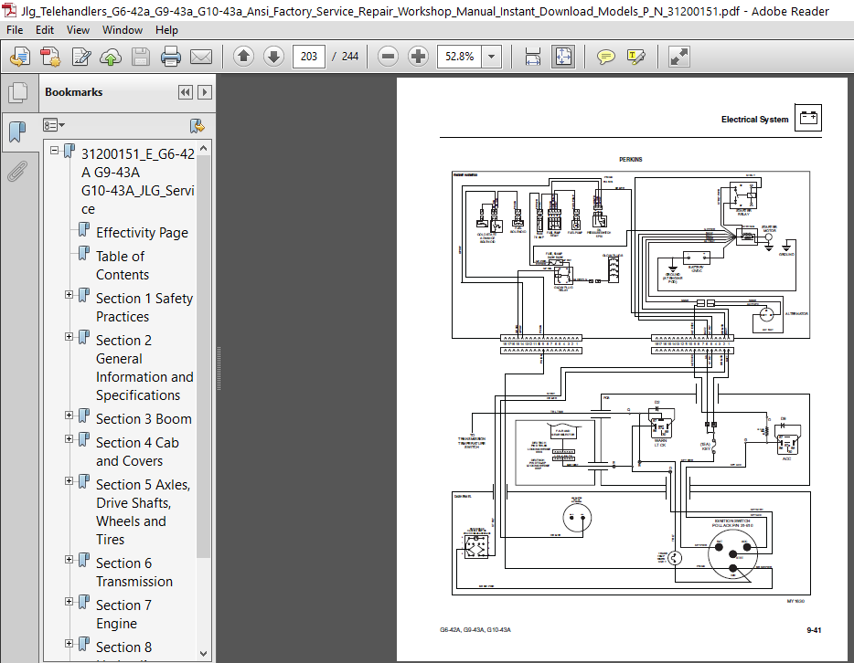
Section 9 Electrical System................................................................................................................163
9.1 Electrical Component Terminology...................................................................................................165
9.1.1 General Overview.............................................................................................................165
9.2 Specifications.....................................................................................................................167
9.3 Safety Information.................................................................................................................167
9.4 Fuses and Relays...................................................................................................................167
9.4.1 Engine Compartment...........................................................................................................167
9.4.2 Cab..........................................................................................................................167
9.4.3 Power Control Board..........................................................................................................168
9.4.4 VEC Module - S/N 0160040675 & After including 0160040468 & 0160040672........................................................170
9.4.5 VEC Module - Options S/N 0160040675 & After including 0160040468 & 0160040672................................................171
9.5 Electrical System Schematics.......................................................................................................172
9.5.1 Before S/N 0160011059........................................................................................................172
9.5.2 G6-42A - S/N 0160011059 Thru 0160021194 G9-43A - S/N 0160011059 Thru 0160020822..............................................178
9.5.3 G6-42A - S/N 0160021195 Thru 0160040678 G9-43A/G10-43A - S/N 0160020823 Thru 0160040465 Excluding 0160040468 & 0160040672....184
9.5.4 G6-42A - S/N 0160040678 & After G9-43A/G10-43A - S/N 0160040465 & After including 0160040468 & 0160040672....................194
9.6 Circuit Breakdowns.................................................................................................................200
9.6.1 Constant Power Circuit from Battery..........................................................................................200
9.6.2 Start Circuit................................................................................................................202
9.6.3 Charging Circuit.............................................................................................................205
9.7 Engine Start Circuit...............................................................................................................207
9.7.1 Starter......................................................................................................................207
9.8 Charging Circuit...................................................................................................................208
9.8.1 Alternator...................................................................................................................208
9.9 Window Wiper/Washer Windshield Wiper Motor.........................................................................................209
9.9.1 Windshield/Rear Window Washer Reservoir......................................................................................210
9.10 Cab Heater and Fan................................................................................................................210
9.10.1 Cab Heater Controls.........................................................................................................210
9.11 Solenoids and Senders.............................................................................................................211
9.11.1 Fuel Shut-off Solenoid......................................................................................................211
9.11.2 Park Brake Solenoid Valve...................................................................................................212
9.11.3 Transmission Solenoid Valves................................................................................................214
9.11.4 Transmission Temperature Sender.............................................................................................214
9.11.5 Engine Coolant Temperature Sender / Switch..................................................................................215
9.11.6 Engine Oil Pressure Sender..................................................................................................216
9.11.7 Fuel Level Sender...........................................................................................................216
9.11.8 Front and Rear Axle Proximity Sensors.......................................................................................217
9.12 Display Monitor and Gauges........................................................................................................217
9.12.1 Analog Gauges...............................................................................................................217
9.13 Dash Switches.....................................................................................................................218
9.13.1 Ignition Key Switch.........................................................................................................218
9.13.2 Dash Switches...............................................................................................................219
9.14 Variable Displacement Pump Control (G9-43A/G10-43A S/N 0160040675 and After including 0160040468 & 016040672).....................220
9.14.1 Pump Displacement Analyzer Software Version A...............................................................................220
9.14.2 Diagnostics Menu............................................................................................................221
9.15 Hand Held Analyzer (G9-43A/G10-43A S/N 0160040675 and After including 0160040468 & 016040672).....................................222
9.15.1 Analyzer Usage..............................................................................................................222
9.15.2 Analyzer Software - Version A...............................................................................................223
9.16 Joystick Fault Codes (G9-43A/G10-43A S/N 0160040675 and After including 0160040468 & 016040672)...................................224
9.17 Engine Indicator Lamps - Perkins..................................................................................................229
9.18 SAE Diagnostic Trouble Codes and Fault Codes - Cummins............................................................................230
PLEASE NOTE:
- This is the SAME exact manual used by your dealers to fix your vehicle.
- The same can be yours in the next 2-3 mins as you will be directed to the download page immediately after paying for the manual.
- Any queries / doubts regarding your purchase, please feel free to contact [email protected]


Mac Kristian –
Everything worked. No problem logging in for access to the manuals. Thank you.