

Instruction Manual for AC Generators QAS 125-150 Volvo – PDF DOWNLOAD
DESCRIPTION:
Instruction Manual for AC Generators QAS 125-150 Volvo – PDF DOWNLOAD
Introduction:
The policy of Atlas Copco is to provide the users of their equipment with safe, reliable and efficient products. Factors taken into account are among others:
– the intended and predictable future use of the products, and the
environments in which they are expected to operate,
– applicable rules, codes and regulations,
– the expected useful product life, assuming proper service and
maintenance,
– providing the manual with up-to-date information.
Before handling any product, take time to read the relevant instruction manual. Besides giving detailed operating instructions, it also gives specific information about safety, preventive maintenance, etc. Keep the manual always at the unit location, easy accessible to the operating personnel.
- See also the safety precautions of the engine and possible other equipment, which are separately sent along or are mentioned on the equipment or parts of the unit. These safety precautions are general and some statements will therefore not always apply to a particular unit.
- Only people that have the right skills should be allowed to operate, adjust, perform maintenance or repair on Atlas Copco equipment. It is the responsibility of management to appoint operators with the appropriate training and skill for each category of job.
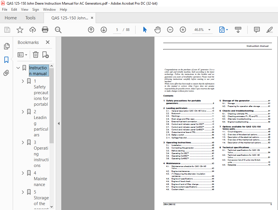
TABLE OF CONTENTS:
Instruction Manual for AC Generators QAS 125-150 Volvo – PDF DOWNLOAD
Instruction manual………………………………………………… 5
1 Safety precautions for portable generators……………………… 6
1.1 Introduction…………………………………………… 6
1.2 General safety precautions………………………………. 6
1.3 Safety during transport and installation………………….. 7
1.4 Safety during use and operation………………………….. 7
1.5 Safety during maintenance and repair……………………… 8
1.6 Tool applications safety………………………………… 9
1.7 Battery safety precautions………………………………. 9
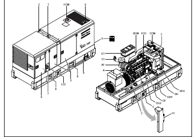
2 Leading particulars…………………………………………..10
2.1 General description QAS 125-150 Volvo……………………..10
2.2 Bodywork……………………………………………….11
2.3 Markings……………………………………………….11
2.4 Drain plugs and filler caps………………………………11
2.5 External fuel tank connection…………………………….12
2.6 Control and indicator panel Qc1002™……………………….12
2.6.1 General description Qc1002™ control panel…………….12
2.6.2 Qc1002™ Module…………………………………….13
2.6.3 Pushbutton and LED functions………………………..13
2.6.4 Qc1002™ Menu Overview………………………………13
2.6.5 Qc1002™ Menu Description……………………………15
2.6.6 Remote start operation……………………………..18
2.6.7 Fail classes………………………………………18
2.7 Control and indicator panel Qc2002™……………………….18
2.7.1 General description Qc2002™ control panel…………….18
2.7.2 Qc2002™ Module…………………………………….19
2.7.3 Pushbutton and LED functions………………………..19
2.7.4 Qc2002™ Menu Overview………………………………20
2.7.5 Qc2002™ Menu Description……………………………22
2.7.6 Fail classes………………………………………27
2.8 Control and indicator panel Qc4002™……………………….28
2.8.1 General description Qc4002™ control panel…………….28
2.8.2 Qc4002™ Module…………………………………….28
2.8.3 Pushbutton and LED functions………………………..29
2.8.4 Qc4002™ Menu Overview………………………………30
2.8.5 Passwords…………………………………………42
2.8.6 Fail Classes………………………………………42
2.8.7 Languages…………………………………………42
2.8.8 Standard modes…………………………………….42
2.8.9 Diagnostics menu…………………………………..43
2.8.10 Standard applications……………………………..43
2.8.11 Parallelling……………………………………..46
2.8.12 Overview of applications…………………………..47
2.9 Output terminal board (TB)……………………………….48
2.10 Battery switch…………………………………………48
2.11 Spillage free skid……………………………………..48
3 Operating instructions………………………………………..49
3.1 Installation……………………………………………49
3.2 Connecting the generator…………………………………49
3.2.1 Precautions for non-linear and sensitive loads………..49
3.2.2 Quality, minimum section and maximum length of cables….49
3.2.3 Connecting the load………………………………..50
3.3 Before starting…………………………………………50
3.4 Operating Qc1002™……………………………………….50
3.4.1 Starting Qc1002™…………………………………..50
3.4.2 During operation Qc1002™……………………………50
3.4.3 Stopping Qc1002™…………………………………..51
3.5 Operating Qc2002™……………………………………….51
3.5.1 Starting Qc2002™…………………………………..51
3.5.2 During operation Qc2002™……………………………51
3.5.3 Stopping Qc2002™…………………………………..52
3.6 Operating Qc4002™……………………………………….52
3.6.1 Starting Qc4002™…………………………………..52
3.6.2 During operation Qc4002™……………………………52
3.6.3 Stopping Qc4002™…………………………………..52
4 Maintenance………………………………………………….53
4.1 Maintenance schedule for QAS 125-150 Volvo…………………53
4.2 Engine maintenance………………………………………54
4.3 (*) Measuring the alternator insulation resistance………….54
4.4 Engine oil specifications………………………………..54
4.4.1 Specifications PAROIL………………………………54
4.4.2 PAROIL 5W40 and PAROIL 15W40………………………..54
4.5 Engine oil level check…………………………………..55
4.6 Engine oil and oil filter change………………………….55
4.7 Engine coolant specifications…………………………….55
4.7.1 Specifications PARCOOL EG…………………………..55
4.8 Coolant check…………………………………………..56
4.8.1 Monitoring coolant condition………………………..56
4.8.2 Topping up of coolant………………………………56
4.8.3 Replacing the coolant………………………………56
5 Storage of the generator………………………………………57
5.1 Storage………………………………………………..57
5.2 Preparing for operation after storage……………………..57
6 Checks and troubleshooting…………………………………….57
6.1 Checking voltmeter P4……………………………………57
6.2 Checking ammeters P1, P2 and P3…………………………..57
6.3 Alternator troubleshooting……………………………….58
6.4 Engine troubleshooting…………………………………..58
7 Options available for QAS 125-150 Volvo units……………………59
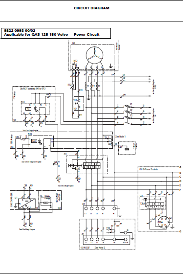
7.1 Circuit diagrams………………………………………..59
7.2 Overview of the electrical options………………………..59
7.3 Description of the electrical options……………………..59
7.3.1 Automatic battery charger…………………………..59
7.3.2 Engine coolant heater………………………………59
7.3.3 Outlet sockets (S)…………………………………60
7.3.4 Dual voltage (DV)………………………………….61
7.3.5 Dual frequency…………………………………….61
7.3.6 “Electricité de France” (EDF)……………………….62
7.3.7 IT-relay………………………………………….62
7.3.8 Integrated spark arrestor…………………………..62
7.3.9 Air inlet shut-off valve……………………………62
7.3.10 COSMOS™ retrofit kit………………………………63
7.4 Overview of the mechanical options………………………..63
7.5 Description of the mechanical options……………………..63
7.5.1 Quick couplings……………………………………63
8 Technical specifications………………………………………64
8.1 Technical specifications for QAS 125 Volvo…………………64
8.1.1 Readings on gauges…………………………………64
8.1.2 Settings of switches……………………………….64
8.1.3 Specifications of the engine/alternator/unit………….64
8.2 Technical specifications for QAS 150 Volvo…………………67
8.2.1 Readings on gauges…………………………………67
8.2.2 Settings of switches……………………………….67
8.2.3 Specifications of the engine/alternator/unit………….67
8.3 Conversion list of SI units into British units……………..70
8.4 Dataplate………………………………………………70
Circuit diagrams…………………………………………………..71
IMAGES PREVIEW OF THE MANUAL:
VIDEO PREVIEW OF THE MANUAL:

PLEASE NOTE:
- This is the SAME manual used by the dealers to troubleshoot any faults in your vehicle. This can be yours in 2 minutes after the payment is made.
- Contact us at [email protected] should you have any queries before your purchase or that you need any other service / repair / parts operators manual.
S.V


