

GEHL Mustang 5.46GB Service Manual COMPLETE SET – PDF DOWNLOAD
FILE DETAILS:
GEHL Mustang 5.46GB Service Manual COMPLETE SET – PDF DOWNLOAD
Size: 5.46GB
Format: PDF
Language: English
Brand: GEHL Mustang Machine
Type of machine: Articulated Loader, Compact Excavator, Compact Loader, Skid Steer Loader ,Telehandlers, Track Loader,Wheel Loader
Updated: 2020
Type of Documents: Service Manuals, Some Parts and Operator Manual
DETAIL CONTENTS:
GEHL Mustang 5.46GB Service Manual COMPLETE SET – PDF DOWNLOAD
Models Contents Detail:
1/ GEHL (2,54GB)
2/ MUSTANG (2,91GB)
1/ GEHL
GEHL\GEHL Articulated Loader AL140 AL240 AL340 Service Manual 918274.pdf
GEHL\GEHL Articulated Loader AL440 _ AL540 Service Manual 918275.pdf
GEHL\GEHL Compact Excavator 170Z_Z17 Service Manual_50940107-RevA.PDF
GEHL\GEHL Compact Excavator 170Z_Z17(GEN-NXT2) Service Manual_50940307-REVA.pdf
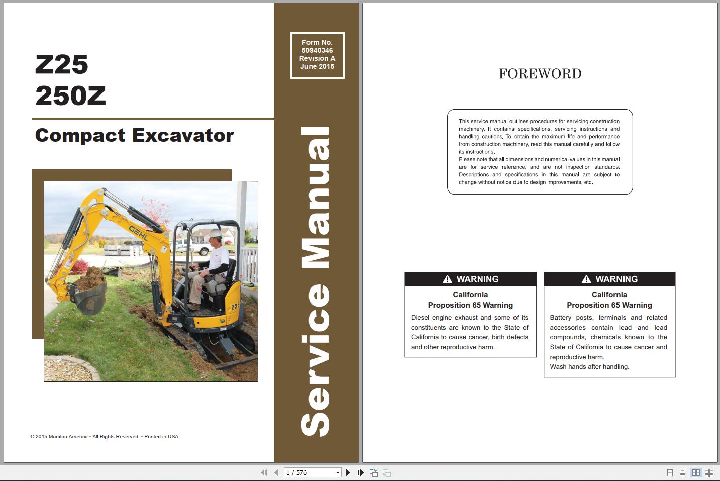
GEHL\GEHL Compact Excavator 250Z_Z25 Service Manual_50940346.pdf
GEHL\GEHL Compact Excavator 270Z 350Z(Z27-Z35) Service Manual_50940109-RevA.PDF
GEHL\GEHL Compact Excavator 350Z_Z35(GEN-NXT2) Service Manual_50940137-RevA.PDF
GEHL\GEHL Compact Excavator 450Z_Z45 Service Manual_50940111-REVA.pdf
GEHL\GEHL Compact Excavator 450Z_Z45(GEN-NXT2) Service Manual_50940272-REVA.pdf
GEHL\GEHL Compact Excavator 550Z_Z55 Service Manual_50940331.pdf
GEHL\GEHL Compact Excavator 800Z_Z80 (GEN-NXT2) Service Manual_50940321-RevA.pdf
GEHL\GEHL Compact Excavator 800Z_Z80 (GEN-NXT2) Service Manual_50940326.pdf
GEHL\GEHL Compact Excavator 800Z_Z80 Service Manual_50940113-RevA.PDF
GEHL\GEHL Compact Excavator M08_80M Service Manual_50940518.pdf
GEHL\GEHL Compact Excavator ME3803ZT Service Manual_918207.pdf
GEHL\GEHL Compact Excavator Z17 GEN 2 170Z NXT2 Service Manual 50940307.pdf
GEHL\GEHL Compact Excavator Z80 SN 00701 and Up 800Z SN 00701 and Up Service Manual 50940321.pdf
GEHL\GEHL Compact Excavators 1202 Parts Manual.pdf
GEHL\GEHL Compact Excavators 153 193 223 Service Manual 918161.pdf
GEHL\GEHL Compact Excavators 802 Service Manual 918158.pdf
GEHL\GEHL Compact Excavators Z27 270Z Z35 350Z Service Manual 50940109.pdf
GEHL\GEHL Compact Excavators Z45 450Z Service Manual 50940111.pdf
GEHL\GEHL Compact Excavators Z55 550Z Service Manual 50940331.pdf
GEHL\GEHL Compact Track Loader CTL60,70,80 Parts Manual.pdf
GEHL\GEHL Compact Track Loader RT175 RT175 Gen 2 RT210 RT210 Gen 2 RT250 Service Manual 50940164.pdf
GEHL\GEHL Compact Track Loader Z45 Gen2_450Z Nxt2 Service Manual 50940272.pdf
GEHL\GEHL Compact Track Loaders CTL55 Service Manual 917366.pdf
GEHL\GEHL Compact Track Loaders CTL60 Service Manual 908310.pdf
GEHL\GEHL Compact Track Loaders CTL65 Service Manual 917337.pdf
GEHL\GEHL Compact Track Loaders CTL70 Service Manual 917100.pdf
GEHL\GEHL Compact Track Loaders CTL75 Service Manual 917342.pdf
GEHL\GEHL Compact Track Loaders CTL80 Service Manual 908311.pdf
GEHL\GEHL Compact Track Loaders CTL85 Service Manual 917338.pdf
GEHL\GEHL Forage Harverter 1040 Parts Manual.pdf
GEHL\GEHL Skid Loader 4625 Service Manual 907212.pdf
GEHL\GEHL Skid-Steer Loaders 1640E Mustang 2012 Service Manual 917400.pdf
GEHL\GEHL Skid-Steer Loaders 4010 Service Manua 903931.pdf
GEHL\GEHL Skid-Steer Loaders 4640E 5240E Power2 Mustang 2056 Series II with Tier 4i Yanmar 4TNV98-ZNMS Engine Service Manual 50950037.pdf
GEHL\GEHL Skid-Steer Loaders 5625 Service Manual 907245.pdf
GEHL\GEHL Skid-Steer Loaders 6620 Series Service Manual 904167.pdf
GEHL\GEHL Skid-Steer Loaders GEHL 5635 6635 Service Manual 907285.pdf
GEHL\GEHL Skid-Steer Loaders R135 150 165 Mustang 1350R 1500R 1650R Service Manual 50940256.pdf
GEHL\GEHL Skid-Steer Loaders R135 Gehl R150 Gehl R165 Mustang 1350R Mustang 1500R Mustang 1650R Service Manual.pdf
GEHL\GEHL Skid-Steer Loaders R190 220 260 Mustang 1900R 2200R 2600R Service Manual 50950134.pdf
GEHL\GEHL Skid-Steer Loaders SL3635 SL3935 Service Manual 908269.pdf
GEHL\GEHL Skid-Steer Loaders SL3640, SL3840 and SL4240 Service Manual 917170.pdf
GEHL\GEHL Skid-Steer Loaders SL4635 and SL4835 Service Manual 907809.pdf
GEHL\GEHL Skid-Steer Loaders SL4640 SL4840 SL5640 SL6640 Service Manual 917002.pdf
GEHL\GEHL Skid-Steer Loaders SL4640E And SL6640E Service Manual 917231.pdf
GEHL\GEHL Skid-Steer Loaders SL5635 and SL6635 Series II Service Manual 907864.pdf
GEHL\GEHL Skid-Steer Loaders SL7600 SL7800 Service Manual 908275.pdf
GEHL\GEHL Skid-Steer Loaders SL7610 SL7710 (EU) and SL7810 Service Manual 917033.pdf
GEHL\GEHL Skid-Steer Loaders SL7610, SL7710 (EU) and SL7810 Service Manual.pdf
GEHL\GEHL Skid-Steer Loaders SL7810E Service Manual 917228.pdf
GEHL\GEHL Skid-Steer Loaders V270 V330 GEN 2 Mustang 2700V 3300V NXT2 Service Manual 50950192.pdf
GEHL\GEHL Skid-Steer Loaders V270 V330 Mustang 2700V 3300V Skid-Steer Loaders Service Manual 917435.pdf
GEHL\GEHL Skid-Steer Loaders V400 Mustang 4000V Service Manual 50950064.pdf
GEHL\GEHL Telescopic Handler 1083 Parts Manual.pdf
GEHL\GEHL Telescopic Handler 883 1083 Service Manual 907330.pdf
GEHL\GEHL Telescopic Handler CT5-16 TURBO CT5-16 Service Manual 913239.pdf
GEHL\GEHL Telescopic Handler CT6-18 TURBO CT6-18 Service Manual 913238.pdf
GEHL\GEHL Telescopic Handler CT7-23 TURBO Service Manual 913234.pdf
GEHL\GEHL Telescopic Handler DL6 DL7 DL8 DL9 DL10 DL11 DL12 Service Manual 907871.pdf
GEHL\GEHL Telescopic Handler RS5-19 Service Manual 913301.pdf
GEHL\GEHL Telescopic Handler RS5-34 RS6-34 Service Manual 913241.pdf
GEHL\GEHL Telescopic Handler RS6-42 RS8-42 RS8-44 RS10-44 RS10-55 RS12-42 Service Manual 913233.pdf
GEHL\GEHL Wheel Loader 280 Operator Manual.pdf
GEHL\GEHL Wheel Loader 418 418T Service Manual 50940186.pdf
GEHL\GEHL Wheel Loader 480 Operator Manual.pdf
GEHL\GEHL Wheel Loader 502 602 652 Service Manual 918157.pdf
GEHL\GEHL Wheel Loader 521 Operator Manual.pdf
GEHL\GEHL Wheel Loader 521 Wheel Loader Service Manual 50940187.pdf
GEHL\GEHL Wheel Loader 680 Operator Manual.pdf
GEHL\GEHL Wheel Loader 721 721T Service Manual 50940188.pdf
GEHL\GEHL Wheel-Steer Loader 280 Service Manual 918114.pdf
GEHL\GEHL Wheel-Steer Loader 480 All Service Manual 918117.pdf
GEHL\GEHL Wheel-Steer Loader 480 Service Manual.pdf
GEHL\GEHL Wheel-Steer Loader 480T Service Manual 918120.pdf
GEHL\GEHL Wheel-Steer Loader 680 Service Manual 343010001.pdf
GEHL\GEHL Wheel-Steer Loader AWS36 and AWS46 Service Manual 918265.pdf
GEHL\GEHL Windrow Merger 1160 Parts Manual.pdf
2/ MUSTANG
MUSTANG\Mustang Articulated Loader 608 708 708T(650-750-T750) Service Manual_50940441.pdf
MUSTANG\Mustang Articulated Loader AL106 AL206 AL306(Series 100,200,300) Service Manual_918360.pdf
MUSTANG\Mustang Articulated Loader AL406 AL506(Series 400,500) Service Manual_50940008.pdf
MUSTANG\Mustang Compact Excavator 2803ZT Service Manual_918279-REVA.pdf
MUSTANG\Mustang Compact Excavator 5003ZT Sevice Manual_918178-REVB.pdf
MUSTANG\Mustang Compact Excavator ME12002 Service Manual_909768-REVB.pdf
MUSTANG\Mustang Compact Excavator ME1503 ME1903 ME2203 Service Manual_918174.pdf
MUSTANG\Mustang Compact Excavator ME2503-3003-3503-3703 Service Manual_918149-REVA.pdf
MUSTANG\Mustang Compact Excavator ME5002 ME6002 ME6502 Service Manual_918172.pdf
MUSTANG\Mustang Compact Excavator ME6003 Service Manual_918175.pdf
MUSTANG\Mustang Compact Excavator ME7503ZT Service Manual_918165.pdf
MUSTANG\Mustang Compact Excavator ME80003 Service Manual_918170.pdf
MUSTANG\Mustang Compact Excavator ME8002 Service Manual_918173.pdf
MUSTANG\Mustang Compact Loader 1350RT 1650RT(RT135-RT165) Service Manual_50950470.pdf
MUSTANG\Mustang Compact Loader 1750RT 2100RT 2500RT Service Manual_50940165-REVC.pdf
MUSTANG\Mustang Compact Loader 1850RT 2150RT 2550RT(RT185-RT215-RT255) Service Manual_50940649.pdf
MUSTANG\Mustang Compact Loader RT105_1050RT Service Manual_50950457.pdf
MUSTANG\Mustang Skid Steer Loader 1050R_R105 Service Manual_50950298.pdf
MUSTANG\Mustang Skid Steer Loader 1350R 1500R(R135-R150) Service Manual_50940256-REVB.pdf
MUSTANG\Mustang Skid Steer Loader 1900R 2200R 2600R(R190-R220-R260) Service Manual_50950134.pdf
MUSTANG\Mustang Skid Steer Loader 2012_1640E Service Manual_917400-RevA.PDF
MUSTANG\Mustang Skid Steer Loader 2022 2032 Service Manual_908272.PDF
MUSTANG\Mustang Skid Steer Loader 2026 2041 Service Manual_917171-RevA.PDF
MUSTANG\Mustang Skid Steer Loader 2040 2050 Service Manual_001-49966.PDF
MUSTANG\Mustang Skid Steer Loader 2042 2044 2054 Service Manual_000-78025.PDF
MUSTANG\Mustang Skid Steer Loader 2056 Service Manual_917438-RevB.PDF
MUSTANG\Mustang Skid Steer Loader 2056(4640E-5240E Power2) Service Manual_50950037.PDF
MUSTANG\Mustang Skid Steer Loader 2060 2070 Service Manual_001-69975.PDF
MUSTANG\Mustang Skid Steer Loader 2060 Service Manual_001-16966.PDF
MUSTANG\Mustang Skid Steer Loader 2064 2074 Service Manual_000-88025.PDF
MUSTANG\Mustang Skid Steer Loader 2066 2076 2086 Service Manual_917098.PDF
MUSTANG\Mustang Skid Steer Loader 2066 2076 2086(5640E-6640E) Service Manual_917292.PDF
MUSTANG\Mustang Skid Steer Loader 2076 2086(SL4640E_4840E-4640-6640E) Service Manual_917231.pdf
MUSTANG\Mustang Skid Steer Loader 2095 2105 Service Manual_908278.PDF
MUSTANG\Mustang Skid Steer Loader 2099 2107(EU) 2109 Service Manual_917036.PDF
MUSTANG\Mustang Skid Steer Loader 2109(Cummins Engine) Service Manual_917229.PDF
MUSTANG\Mustang Skid Steer Loader 2700V 3300V NXT2(V270-V330) Service Manual_50950192.pdf
MUSTANG\Mustang Skid Steer Loader 2700V_3300V(V270-V330) Service Manual_917435-RevB.PDF
MUSTANG\Mustang Skid Steer Loader 332 342 442 552 Service Manual_087-00184.pdf
MUSTANG\Mustang Skid Steer Loader 4000V_V400 Service Manual_50950064.PDF
MUSTANG\Mustang Skid Steer Loader 4200V_V420 Service Manual_50950421.pdf
MUSTANG\Mustang Skid Steer Loader 920 930A Service Manual_008-12909.pdf
MUSTANG\Mustang Skid Steer Loader 930 940 960 Service Manual_000-12909.pdf
MUSTANG\Mustang Skid Steer Loader SL7610 SL7710 SL7810 Service Manual_917033.PDF
MUSTANG\Mustang Telehandler 519 Service Manual_913302-RevA.pdf
MUSTANG\Mustang Telehandler 634 Service Manual_913251.pdf
MUSTANG\Mustang Telehandler 642 844 Service Manual_913250.pdf
MUSTANG\Mustang Telehandlers 742 944 1155 Service Manual_913237-RevB.pdf
MUSTANG\Mustang Track Loader 3200VT_VT320 Service Manual_50940548.pdf
MUSTANG\Mustang Track Loader MTL16 Service Manual_908312-RevC.PDF
MUSTANG\Mustang Track Loader MTL20 Service Manual_917101.PDF
MUSTANG\Mustang Track Loader MTL25 Service Manual_908313-RevC.PDF
MUSTANG\Mustang Track Loader MTL312 Service Manual_917367-RevB.PDF
MUSTANG\Mustang Track Loader MTL316 Service Manual_917339-RevC.PDF
MUSTANG\Mustang Track Loader MTL320 Service Manual_917343-RevC.PDF
MUSTANG\Mustang Track Loader MTL325 Service Manual_917340-RevC.PDF
MUSTANG\Mustang Wheel Loader 318 418(ML42-ML43) Service Manual_50940189-REVA.pdf
MUSTANG\Mustang Wheel Loader 520 620(ML25) Service Manual_50940190-REVA.pdf
MUSTANG\Mustang Wheel Loader ML28 Service Manual_918133.PDF
MUSTANG\Mustang Wheel Loader ML360 ML460 Service Manual_918294-RevA.PDF
MUSTANG\Mustang Wheel Loader ML48 Service Manual_918136.PDF
MUSTANG\Mustang Wheel Loader ML48T_480T Service Manual_918139.PDF
MUSTANG\Mustang Wheel Loader ML68 Service Manual_918142.PDF
TABLE OF CONTENTS:
GEHL Mustang 5.46GB Service Manual COMPLETE SET – PDF DOWNLOAD
GEHL:
CHAPTER 1
GENERAL CAUTIONS FOR MAINTENANCE WORK
1-1 Correct Work 1-1-1
1-2 Safety Precautions 1-2-1
1-3 Preparations 1-3-1
1-4 Cautions for Disassembly and Reassembly 1-4-1
1-5 Cautions for Removal and Installation of Hydraulic Equipment 1-5-2
1-6 Cautions for Removal and Installation of Hydraulic Piping 1-6-2
1-7 Cautions for Handling Seals 1-7-3
1-8 Correct Installation of Hydraulic Hose 1-8-3
1-9 Specifications of Hydraulic Hose 1-9-6
1-10 Air Release of Hydraulic Equipment 1-10-8
CHAPTER 2
TECHNICAL DATA
2-1 Specifications 2-1-1
2-2 Outline Drawing and Working Area 2-2-1
2-3 Weight List of Main Parts 2-3-1
2-4 Lifting Capacity List 2-4-1
2-5 Specifications for Attachment 2-5-1
2-6 Periodic Inspection and Servicing 2-6-1
2-7 Fuel, Lube Oil and Grease Recommended 2-7-1
2-8 Hydraulic Circuit Schematic 2-8-1
2-9 Wiring Diagram 2-9-1
CHAPTER 3
SERVICE STANDARDS
3-1 Machine Performance 3-1-1
3-2 Engine 3-2-1
3-3 Undercarriage 3-3-1
3-3-1 Rubber Track Specifications 3-3-1
3-3-2 Common Specifications of Rubber Crawlers 3-3-2
3-4 Controls 3-4-1
3-5 Hydraulic Equipment 3-5-1
3-5-1 Hydraulic Cylinders 3-5-1
3-6 Implement 3-6-1
3-6-1 Front Attachments 3-6-1
3-6-2 Blade Moving Device 3-6-2
3-6-3 Bucket Teeth 3-6-2
3-7 List of Tightening Torque 3-7-1
3-7-1 Machine 3-7-1
3-7-2 Engine 3-7-6
3-8 Pressure Adjustment 3-8-1
3-8-1 Relief Valves 3-8-1
3-8-2 Swing Brake Valve 3-8-4
3-8-3 Cut-Off Valve 3-8-5
CHAPTER 4
ENGINE
4-1 Safety 4-1-1
4-1-1 Safety Statements 4-1-1
4-1-2 Safety Precautions 4-1-2
4-2 Engine 4-2-1
4-2-1 Before You Begin Servicing 4-2-1
4-2-2 Introduction 4-2-2
4-2-3 Special Service Tools 4-2-3
4-2-4 Measuring Instruments 4-2-5
4-2-5 Cylinder Head 4-2-7
4-2-6 Disassembly of rocker arm assembly 4-2-10
4-2-7 Measuring and Adjusting Valve Clearance 4-2-20
4-2-8 Crankshaft and Camshaft Components 4-2-22
4-3 Fuel System 4-3-1
4-3-1 Before You Begin Servicing 4-3-1
4-3-2 Introduction 4-3-2
4-3-3 Fuel System Specifications and Tools 4-3-6
4-3-4 Fuel System Diagram 4-3-8
4-3-5 Fuel System Components 4-3-9
4-4 Cooling System 4-4-1
4-4-1 Before You Begin Servicing 4-4-1
4-4-2 Introduction 4-4-2
4-4-3 Cooling System Diagram 4-4-2
4-4-4 Engine Coolant Pump Components 4-4-3
4-4-5 Engine Coolant System Check 4-4-4
4-4-6 Engine Coolant Pump 4-4-4
4-5 Lubrication System 4-5-1
4-5-1 Before You Begin Servicing 4-5-1
4-5-2 Introduction 4-5-2
4-5-3 Oil Pump Service Information 4-5-2
4-5-4 Lubrication System Diagram 4-5-3
4-5-5 Checking Engine Oil Pressure 4-5-4
4-5-6 Trochoid Oil Pump 4-5-4
4-6 Starter Motor 4-6-1
4-6-1 Before You Begin Servicing 4-6-1
4-6-2 Introduction 4-6-2
4-6-3 Starter Motor Specifications 4-6-2
4-6-4 Starter Motor Troubleshooting 4-6-3
4-6-5 Starter Motor Components 4-6-4
4-6-6 Starter Motor 4-6-5
4-7 Alternator 4-7-1
4-7-1 Before You Begin Servicing 4-7-1
4-7-2 Introduction 4-7-2
4-7-3 Alternator Specifications 4-7-2
4-7-4 Alternator Troubleshooting 4-7-3
4-7-5 Alternator Components 4-7-4
4-7-6 Alternator Wiring Diagram 4-7-5
4-7-7 Alternator Standard Output 4-7-6
4-7-8 Alternator 4-7-7
4-8 Electric Wiring 4-8-1
4-8-1 Electric Wiring Precautions 4-8-1
4-9 Failure Diagnosis 4-9-1
4-9-1 Special Service Tools 4-9-1
4-9-2 Troubleshooting By Measuring Compression Pressure 4-9-2
4-10 Troubleshooting 4-10-1
4-10-1 Quick Reference Table for Troubleshooting 4-10-1
CHAPTER 5
ELECTRIC SYSTEM
5-1 Electric Equipment of Machine 5-1-1
5-1-1 Parts Layout of Electrical Equipment 5-1-1
5-1-2 LCD Monitor and Alarm Systems 5-1-7
5-2 Circuit Description of Engine Start and Stop 5-2-1
5-2-1 Engine Start and Stop 5-2-1
5-2-2 Battery charge 5-2-3
5-3 Automatic Deceleration System 5-3-1
5-3-1 Main Components and Wiring Diagram 5-3-1
5-3-2 Function and Control 5-3-3
5-4 Error Code List 5-4-1
CHAPTER 6
HYDRAULIC SYSTEM
6-1 Outline 6-1-1
6-1-1 Control Valve Operation 6-1-3
6-1-2 Additional Operation of Control Valve 6-1-4
6-2 Circuit Operation 6-2-1
6-2-1 Boom 6-2-1
6-2-2 Arm 6-2-2
6-2-3 Bucket 6-2-3
6-2-4 Swing 6-2-4
6-2-5 Boom Swing 6-2-5
6-2-6 Blade 6-2-6
6-2-7 Travel 6-2-7
6-2-8 Non-Deviation Travel (with Boom, Arm, Bucket or Boom Swing Operation) 6-2-8
6-2-9 Simultaneous Operation of Boom Up and Arm Retract 6-2-9
6-2-10 Simultaneous Operation of Boom Up and Bucket 6-2-10
6-2-11 Simultaneous Operation of Boom Up and Swing 6-2-11
6-2-12 Simultaneous Operation of Arm and Bucket 6-2-12
6-2-13 Hydraulic P T O 6-2-13
6-2-14 Quick Coupler (Quick coupler spec ) 6-2-14
6-2-15 Travel Alarm 6-2-15
6-2-16 Auto Deceleration (Optional) 6-2-16
6-3 Hydraulic Pump 6-3-1
6-4 Control Valve 6-4-1
6-5 Pilot Valve 6-5-1
6-6 Swing Motor 6-6-1
6-7 Travel Motor 6-7-1
6-8 Proportional solenoid valve 6-8-1
6-9 Pilot Check Valve (For Quick Coupler Circuit) 6-9-1
6-10 2-way valve 6-10-1
CHAPTER 7
ADJUSTMENT AND REPAIR
7-1 Engine and Electric Equipment 7-1-1
7-1-1 Removal and Reinstallation of Engine 7-1-1
7-1-2 Removal and Reinstallation of Starter Motor 7-1-13
7-1-3 Removal and Reinstallation of Radiator and Oil Cooler 7-1-15
7-1-4 Removal and Reinstallation of Fan Belt 7-1-20
7-2 Undercarriage 7-2-1
7-2-1 Outline 7-2-1
7-2-2 Points of Reassembly (Rubber Track) 7-2-2
7-2-3 Removal and Reinstallation of Track 7-2-3
7-2-4 Removal and Reinstallation of Travel Motor 7-2-4
7-2-5 Disassembly and Reassembly of Idler 7-2-6
7-2-6 Disassembly and Reassembly of Track Roller 7-2-9
7-2-7 Disassembly and Reassembly of Carrier Roller 7-2-12
7-2-8 Installation of Floating Seal 7-2-14
7-2-9 Drawings of Jig 7-2-15
7-3 Controls 7-3-1
7-3-1 Mechanical Control Linkage 7-3-1
7-3-2 Adjustment of Travel Levers 7-3-3
7-3-3 Adjustment of Blade Lever 7-3-4
7-3-4 Adjustment of Lock Lever 7-3-5
7-4 Swing Bearing 7-4-1
7-5 Hydraulic Equipment 7-5-1
7-5-1 Removal and Reinstallation of Hydraulic Pump 7-5-1
7-5-2 Removal and Reinstallation of Control Valve 7-5-3
7-5-3 Removal and Reinstallation of Pilot Valves (L and R) 7-5-7
7-5-4 Removal and Reinstallation of Swing Motor 7-5-9
7-5-5 Removal and Reinstallation of Swivel Joint 7-5-11
7-5-6 Disassembly and Reassembly of Swivel Joint 7-5-15
7-5-7 Disassembly and Reassembly of Hydraulic Cylinder 7-5-18
7-5-8 Removal and Reinstallation of Hydraulic Oil Tank 7-5-25
7-5-9 Piping Layout 7-5-32
7-6 Work Implements 7-6-1
7-6-1 Removal and Reinstallation of Work Implements 7-6-1
7-6-2 Quick Coupler 7-6-9
7-7 Cabin 7-7-1
7-7-1 Removal and Reinstallation of Cabin 7-7-1
CHAPTER 8
TROUBLESHOOTING
8-1 Non-Breakdowns 8-1-1
8-1-1 Natural Release of Bucket 8-1-1
8-1-2 Discontinuous Arm Movement 8-1-1
8-1-3 Drifting of Upperstructure on Quick Travel Operation 8-1-2
8-1-4 Thermal Shock of Travel Motor 8-1-3
8-1-5 Elongation of Boom Swing Cylinder on 65 degrees Swing 8-1-4
8-1-6 Telescopic Motion of Boom Swing Cylinder with Lock Lever Set to Lock Position 8-1-5
8-1-7 Time Lag on Travel Speed Switching 8-1-6
8-1-8 Fluctuation in Oil Level of Hydraulic Oil Tank Due to Temperature Change 8-1-7
8-1-9 Operation of Quick Coupler Cylinder (for Quick Coupler Type) 8-1-8
8-2 Quick Reference Table for Troubleshooting 8-2-1
APPENDIX
Wiring Diagram
Mustang:
Operation
Important information about this service manual 1-1
Abbreviations/symbols 1-1
Identification of warnings and hazards 1-2
Designated use and exemption from liability 1-2
Type labels and component numbers 1-3
Machine: overview 1-5
Cab Equipment and Controls 1-6
Instrument panel, switches and indicators 1-8
Engine compartment 1-10
Chassis: overview 1-11
SAE/ISO operating controls selector valve 1-12
Tilting the cab 1-13
SAE operating controls (standard) 1-14
ISO operating controls (selectable) 1-15
Boom slew/auxiliary hydraulics pedal 1-16
Dozer blade 1-17
Throttle lever 1-17
Operator’s seat adjustments 1-18
Ventilation 1-19
Cab door latch release 1-20
Interior light 1-21
Tool kit and cab jack handle 1-21
Cab heat control 1-21
Recirculated air mode 1-22
Hydraulics/swiveling and boom rotation pedal adjustment 1-22
Battery master switch 1-22
Specifications
Chassis 2-1
Engine 2-1
Capacities 2-2
Engine Tightening Torques 2-2
Hydraulic system 2-3
Auxiliary hydraulics oil flow* 2-3
Screwable hose burst valve 2-3
Undercarriage/swivel unit 2-4
Dozer blade 2-4
Electrical system 2-4
Sound levels 2-6
Fluid capacities 2-7
Coolant compound table 2-7
Specific tightening torques 2-7
General tightening torques 2-8
Dimensions 2-10
Lift Capacities 2-11
Geometry 2-15
Maintenance
General information care and servicing 3-1
Maintenance decal symbols 3-3
Maintenance decal 3-4
Maintenance schedule 3-5
General Maintenance 3-7
Cab interior 3-8
Exterior of the machine 3-8
I-2 918175/AP0605
Engine compartment 3-8
Screw connections and attachments 3-8
Pivots and hinges 3-8
Lubrication 3-9
Lubrication strip 3-10
Engine 3-10
Changing engine oil and filter 3-11
Air cleaner service 3-12
Fuel system 3-13
Coolant system 3-16
Electrical system 3-17
Alternator 3-20
Checking & adjusting V-belt tension 3-20
Fluids and lubricants 3-23
Pressure check 3-24
General 3-24
Pressure check of variable displacement pump P1 3-24
Pressure check of variable displacement pump P2 3-25
Checking the gear pump P3 pressure 3-26
Checking pilot control pressure 3-27
Gear motor secondary pressure limiting valve 3-28
Measuring ports: overview 3-28
Primary pressure limiting valves 3-29
Test report 3-30
Hydraulic system 3-33
Cab heater filter 3-36
Replacing the inside heater filter 3-36
Engine
4TNV98 engine: overview 4-1
Fuel system 4-3
Removing the cylinder-head cover 4-4
Checking and adjusting valve tip clearance 4-4
Cylinder head bolt tightening order 4-6
Checking the injection nozzles 4-6
Pressure check 4-6
Checking the nozzle jet 4-7
Injection timing 4-8
Adjusting engine idle 4-9
Compression 4-9
Checking the coolant thermostat 4-10
Checking the thermal switch 4-10
Oil pressure switch 4-11
Checking the coolant circuit 4-11
Engine troubleshooting 4-12
Hydraulic System
Hydraulic pump PVD-3B-56P-21G5-4626F 5-1
Pump unit: exploded view 5-3
Control oil unit 5-4
Main valve block 5-5
Ports 5-5
Legend 5-6
Main valve block diagram 5-7
Pressure limiting valves 5-8
Pump assignment 5-9
Drive counterbalancing system 5-10
Pump assignment for drive counterbalancing 5-10
918175/AP0605 I-3
Drive counter-balancing system diagram 5-11
Regeneration – dipper arm section 5-12
Bucket pre-tension 5-12
Boom summation – raise 5-13
Check valve (load retaining valve) 5-14
Flow rate adjustment of auxiliary hydraulics 5-15
Secondary pressure limiting valves for the auxiliary hydraulics (option) 5-16
Pilot valves 5-17
Joystick 5-17
Pilot valve (driving) 5-18
Pilot valve for auxiliary hydraulics 5-20
Pilot valve for dozer blade 5-21
Valves 5-22
7/3 directional valve (changeover valve) 5-22
4/3 directional valve 5-23
Shuttle valve block 5-24
Changeover valve for SAE/ISO controls (option) 5-25
Travel drive 5-26
Function 5-27
2nd speed range function 5-27
Swivel unit 5-29
Parking brake function 5-30
Swivel joint 5-33
Breather filter 5-33
Troubleshooting in the hydraulic system 5-34
Hydraulics diagram A4 5-35
Hydraulics diagram (legend) 5-36
Hydraulics diagram 5-37
Main valve block diagram 5-38
Hydraulics diagram with 3rd control circuit (option) 5-39
Main valve block diagram with 3rd control circuit (option) 5-40
Electrical system
Ohm’s Law (current, voltage, resistance); power 6-1
Measuring equipment, measuring methods 6-1
Cable color coding 6-2
Relays 6-3
Use, mode of function 6-3
Electric units 6-3
Fuse box in instrument panel 6-3
Main fuse box with relays 6-4
Relays 6-4
Socket 6-5
Tip switches on joystick 6-5
Left-hand side joystick 6-5
Right-hand side joystick 6-5
I-4 918175/AP0605
Instrument panel: overview 6-6
Switches: overview 6-7
Alternator 6-7
Starter 6-8
Wiring harness 1000109629: cab roof 6-9
Wiring diagram version 1 6-10
Wiring diagram version 1: legend 6-11
Wiring diagram version 1 6-12
Wiring diagram version 2: legend 6-13
Wiring diagram version 2 6-14
Wiring harness 1000109624 (legend): engine – chassis 6-15
Wiring harness 1000109624: engine – chassis 6-16
Wiring harness 1000109630 (legend) version 1: switches 6-17
Wiring harness 1000109630 version 1: switches 6-18
Wiring harness (legend) version 2: switches A4 6-19
Wiring harness version 2: switches 6-20
Wiring harness 1000109628: armrest 6-21
Wiring harness 1000116138: boom working light 6-22
Options
Air conditioning 7-1
Specific safety instructions 7-1
Installation: overview 7-2
Components 7-2
Counterweight 7-8
Specifications 7-8
Extended dipper arm 7-8
Specifications 7-8
Control circuit hydraulic coupling connections 7-9
3rd control circuit connections 7-9
Auxiliary hydraulics connections 7-10
Fuel-filling pump 7-11
Ports 7-12
Central lubrication system 7-12
Safe load indicator D (safety valve for boom) 7-17
Safe load indicator F (safety valves for boom and dipper arm) 7-19
Position 7-19
DESCRIPTION:
GEHL Mustang 5.46GB Service Manual COMPLETE SET – PDF DOWNLOAD
Mustang:
Introduction:
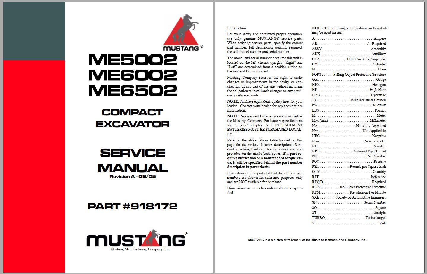
For your safety and continued proper operation, use only genuine MUSTANG® service parts. When ordering service parts, specify the correct part number, full description, quantity required, the unit model number and serial number. The model and serial number decal for this unit is located on the left chassis upright.
- “Right” and “Left” are determined from a position sitting on the seat and facing forward. Mustang Company reserves the right to make changes or improvements in the design or construction of any part of the unit without incurring the obligation to install such changes on any previously delivered units.
- Refer to the abbreviations table located on this page for the various fastener descriptions. Standard attaching hardware torque values are also provided on the inside back cover.
- If a part requires lubrication or a nonstandard torque value, it will be specified behind the part number description in parenthesis. Items shown in the parts list that do not have part numbers are shown for reference purposes only and are NOT available for purchase. Dimensions are in inches unless otherwise specified.
General Cautions for Maintenance Work
1-1 Correct Work
Correct work means the quickest possible completion of according to the correct procedures and the specified standards.
It is important when conducting certain operations always to bear in mind the equipment, tools, gauges, materials, oil
and grease, etc. that you must have ready, as well as items to be checked, adjusted, or disassembled, and cautions
to watch out for.
1-2 Safety Precautions
(1) Never attempt servicing while engine is running or immediately after stopping operation.
(2) Wear work cloths, safety shoes and helmet.
(3) Check the equipment and tools before use. Especially, be sure to check the crane, lifting equipment and tools.
(4) When working together with other persons, allocate everyone’s share of job, arrange the signals and act in concert
with the other persons.
(5) The operation of the crane and slinging work must be performed by qualified persons.
(6) Do not enter or pass under the raised load.
(7) Lift and support the massive parts by crane before removing the installation bolts.
(8) Disconnect cables from battery before repairing the electric system.
(9) Remove the battery when welding the machine.
1-3 Preparations
(1) Check the service record of the machine. (That is, check how many months or hours the machine has been
used since the preceding overhaul, what was the trouble then and what parts were replaced.)
(2) Have all servicing tools ready, i.e., tools, measuring devices (which have received periodic maintenance), containers,
oil & grease, etc.
(3) Have the service literature (operation manual, parts catalog, etc.) ready.
IMAGES PREVIEW OF THE MANUAL:


VIDEO PREVIEW OF THE MANUAL:
PLEASE NOTE:
- This is not a physical manual but a digital manual – meaning no physical copy will be couriered to you. The manual can be yours in the next 2 mins as once you make the payment, you will be directed to the download page IMMEDIATELY.
- This is the same manual used by the dealers inorder to diagnose your vehicle of its faults.
- Require some other service manual or have any queries: please WRITE to us at [email protected]
S.V


