

Doosan Dx15 Dx18 Excavator Service Repair Workshop Manual
FILE DETAILS:
LANGUAGE:ENGLISH
PAGES:513
DOWNLOADABLE:YES
FILE TYPE:PDF
VIDEO PREVIEW OF THE MANUAL:

IMAGES PREVIEW OF THE MANUAL:
DESCRIPTION:
Doosan Dx15 Dx18 Excavator Service Repair Workshop Manual
DOOSAN reserves the right to improve our products in a continuing process to provide the best possible product to the market place. These improvements can be implemented at any time with no obligation to change materials on previously sold products. It is recommended that consumers periodically contact their distributors for recent documentation on purchased equipment. This documentation may include attachments and optional equipment that is not available in your machine’s package. Please call your distributor for additional items that you may require. Illustrations used throughout this manual are used only as a representation of the actual piece of equipment, and may vary from the actual item.
Adjust seat If the driver’s seat is not adjusted correctly, the operator may become easily fatigued and injury and/or damage could result.
- Be sure to adjust the driver’s seat at the beginning of each work period.
- Adjust driver’s seat so that the operator can easily reach the pedals while his back is firmly against the lumbar support of the seat. Before Starting the Engine Do a “prestart” safety check:
- Walk around your machine before getting in the operator’s cab. Look for evidence of leaking fluid, loose fasteners, misaligned assemblies or any other indications of possible equipment hazard.
- All equipment covers and machinery safety guards must be in place, to protect against injury while the machine is being operated.
- Look around the work site area for potential hazards, or people or property that could be at risk while operation is in progress.
- NEVER start the engine if there is any indication that maintenance or service work is in progress, or if a warning tag is attached to controls in the cab.
- A machine that has not been used recently, or is being operated in extremely cold temperatures, could require a warm-up or maintenance service before start-up.
- Check gauges and monitor displays for normal operation before starting the engine. Listen for unusual noises and remain alert for other potentially hazardous conditions at the start of the work cycle.
TABLE OF CONTENTS:
Doosan Dx15 Dx18 Excavator Service Repair Workshop Manual
Safety Precautions 5
Applicable Models 5
To the Operator of a DOOSAN Excavator 6
General Safety Essentials 8
Location of Safety Labels 8
Unauthorized Modifications 8
Work Site Precautions 9
Operation 13
Equipment 19
Maintenance 24
Shipping and Transportation 28
Specification for DX15/DX18
Safety Precautions 5
Applicable Models 5
General Description 7
Component Locations 8
General Dimensions 10
Canopy Model 10
Cabin Model 12
Dimensions and Working Range 14
General Specifications 16
Engine Performance Curves
(ISO 3046 Standard) 18
Engine RPM Standards (For a New Vehicle) 19
Approximate Weight of Workload Materials 20
Performance Tests 22
Excavator Performance Standards 23
Test Conditions 23
Swing Speed Test 23
Boom Swing Test 24
Cylinder Performance Tests 24
Travel Deviation 26
Swivel Turn Measurement 26
Amount of Drag When Swinging is Stopped 26
General Maintenance Procedures
Safety Precautions 5
Applicable Models 5
Welding Precautions and Guidelines 6
Hydraulic System – General Precautions 7
Maintenance Service and Repair Procedure 9
General Precautions 9
Hydraulic System Cleanliness and Oil Leaks 10
Maintenance Precautions for Hydraulic System Service
10
Oil Leakage Precautions 11
Cleaning and Inspection 12
General Guidelines 12
Bearing inspection 13
Track Assembly
Safety Precautions 5
Applicable Models 5
General Description 6
Track Tension 6
Cleaning and Inspection (Wear Limits and
Tolerances) 8
Track Shoes and Links 15
Interchanging Shoe Types 17
Front Idler Roller 18
Lower Roller 20
Track Spring and Track Adjusting Cylinder 22
Sprocket 25
Engine
Safety Precautions 6
Applicable Models 6
General 7
Engine Model and Engine Number 7
Sectional Views 9
Features 13
Performance Curves 14
Engine Specifications 16
Maintenance 17
Troubleshooting 27
Engine 34
Special Tools 34
Rocker Arms and Rocker Shaft 35
Cylinder Head 37
Valve and Valve Spring 41
Intake Manifold and Exhaust Manifold 44
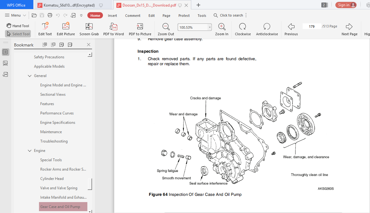
Gear Case and Oil Pump 46
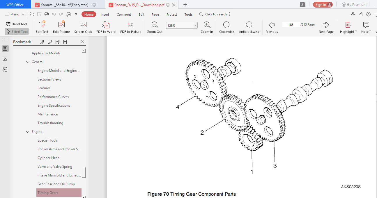
Timing Gears 51
Camshafts (Valve and Pump) 54
Piston and Connecting Rod 58
Crankshaft 64
Cylinder Block 68
Lubricating System 70
General 70
Oil Filter and Oil Pressure Switch 71
Fuel System 72
General 72
Fuel Injection Pump 74
Injection Nozzle 78
Governor System 82
General 82
Torque Spring 84
Engine SP001524
Page 4
Governor 87
Cooling System 89
General 89
Fan and Fan Belt 91
Water Pump 92
Thermostat 92
Engine Coolant Temperature Gauge Unit and Thermo
Switch 93
Air Cleaner 94
Construction 94
Inspection 95
Electrical System 96
General 96
Starter 101
Alternator and Dynamo 108
Glow Plug 116
Key OFF Stop System 116
Glow Plug Timer System 119
Periodic Service Chart 120
Specifications and Standards 121
Engine 121
Lubricating System 125
Fuel System 126
Governor System 127
Cooling System 127
Electrical System 129
Tightening Torque Chart and Sealant Chart 132
Tightening Torque for Common Bolts and Nuts 133
Tightening Torque for Common Plugs 134
Sealant Chart 134
Center Joint (Swivel)
Safety Precautions 5
Applicable Models 5
General Description 6
Parts List 10
Troubleshooting, Testing and Adjustment 12
Inspection 12
Disassembly 13
Reassembly 13
Electrical System
Safety Precautions 5
Applicable Models 5
Troubleshooting – Electrical System 6
Overview 6
Electrical Supply System 7
Engine Starting Circuit 8
Operation During Start Process 8
Operation After Start Process 9
Engine Preheating System 10
Principle of Operation 10
Engine Stop System 11
Operation in Engine Running Mode 11
Operation in Engine Stop Mode 12
Charging System 13
Operation in Charging Mode 13
Boom and Arm
Safety Precautions 5
Applicable Models 5
Front Attachment Pin Specifications 6
Front Attachment – Removal and Installation 7
Arm Removal Procedure 7
Boom Removal Procedure 9
Cleaning and Inspection (Wear Limits and
Tolerances) 10
Installation 14
Arm Installation Procedure 14
Boom Installation Procedure 14
Start-up Procedures 14
PLEASE NOTE:
- This is the SAME MANUAL used by the dealerships to diagnose your vehicle
- No waiting for couriers / posts as this is a PDF manual and you can download it within 2 minutes time once you make the payment.
- Your payment is all safe and the delivery of the manual is INSTANT – You will be taken to the DOWNLOAD PAGE.
- So have no hesitations whatsoever and write to us about any queries you may have : heydownloadss @gmail.com


