

Doosan DX140LC, DX180LC Electrical Wiring Diagrams Manual
FILE DETAILS:
Doosan DX140LC, DX180LC Electrical Wiring Diagrams Manual
Language: English
Size: 3.30 MB
Pages: 129
Format: PDF
Downloadable: YES
DESCRIPTION:
Doosan DX140LC, DX180LC Electrical Wiring Diagrams Manual
INTRODUCTION:
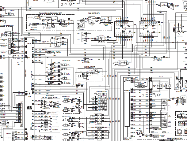
The electrical system for this equipment is DC 24 volts. The rated voltage for all electric components is 24 volts with the exception of the stereo and the air-conditioning control actuator. The system contains two 12 volt batteries connected in series and a three phase AC generator with a rectifier. The electric wiring used in the system is easily identifiable by the insulator color. The color symbols used in the electrical system are listed in the following chart.
TABLE OF CONTENTS:
Doosan DX140LC, DX180LC Electrical Wiring Diagrams Manual
Electrical System
Safety Precautions 7
Applicable Models 7
Introduction 9
Electrical Supply System 10
Engine Starting Circuit 12
Start Operation 12
After Start 14
Engine Preheating System 16
Engine Stop 18
Charging System 20
Monitoring System 21
Instrument Panel 22
Monitoring System Schematic 24
Operation 26
Instruments 26
Warning and Indicator Lights 28
Indication of Warning Lights 28
Indication of Multifunction Gauge and
Letter Information Area 29
Initial Operation 31
Mode Selector Switch 31
Graphic Information Area Display 32
Overview 32
Main Menus for the Graphic Display Area 33
Menu Selector Buttons 33
Main Menu 34
Language 34
Set Clock 35
Filter/Oil Info 35
Adjust Display 36
Electrical System SP001038
Page 4
Set Password 37
Special Menu 38
Entering/Accessing and Exiting/Escaping Menus 38
Special Menu Selections 39
Electronic Hydraulic Control System (e-EPOS) 56
Control System Schematic 56
Power Mode Control 58
Operation 60
Power Mode Control – Circuit Diagram 62
Work Mode Control 64
Operation 65
Work Mode Control – Circuit Diagram 66
Engine Control System 67
Engine Control Dial 68
Engine Control Circuit Diagram 69
Automatic Deceleration Control
(Auto Idle Control) 70
Engine Overheat Protection System 72
Power Boost Mode 74
Operation 74
Power Boost Control – Circuit Diagram 76
Automatic Travel Speed Control 78
Automatic Travel Speed Control – Circuit Diagram 80
Self-diagnostic Function 81
e-EPOS Controller 81
Air Conditioner System 83
Outline 83
Internal and External Filters 84
Air-Conditioning System Layout 86
Air Conditioner/heater Circuit Diagram 87
Air Conditioner/heater Unit 88
Ambient Air Temperature Sensor 93
SP001038
Page 5
Electrical System
Sun Sensor 94
Control Panel 94
Compressor 102
Receiver Dryer 102
Troubleshooting 103
Weight of R134a Gas Used In Machines 105
Refrigerant System Repairs 106
Refrigerant Safe Handling Procedures 106
Repair and Replacement Procedure 107
Refrigerant Recovery 109
Vacuuming Refrigerant System 109
Leakage Check 111
Refrigerant Charging 111
Inspecting System For Leakage 113
Wiper System 114
Wiper Circuit 114
Wiper operation 115
Lighting System 118
Lighting System Circuit Diagram 118
Kind of Light 119
Operation 119
Audio Controller 120
Audio Controller Circuit Diagram 120
VIDEO PREVIEW OF THE MANUAL:

IMAGES PREVIEW OF THE MANUAL:

PLEASE NOTE:
- This is the SAME MANUAL used by the dealerships to diagnose your vehicle
- No waiting for couriers / posts as this is a PDF manual and you can download it within 2 minutes time once you make the payment.
- Your payment is all safe and the delivery of the manual is INSTANT – You will be taken to the DOWNLOAD PAGE.
- So have no hesitations whatsoever and write to us about any queries you may have : heydownloadss @gmail.com


