

Doosan DL08K iTIER4 Engine Shop Manual 950106-00347 – PDF DOWNLOAD
DESCRIPTION:
FOREWORD:
- This maintenance manual is designed to serve as a reference for DOOSAN Infra core (here after DOOSAN’s) customers and distributors who wish to gain basic product knowledge on DOOSAN’s DL08K Diesel engine.
- This economical and high-performance diesel engine (6 cylinders, 4 strokes, in-line, direct injection type) has been so designed and manufactured to be used for the overland transport or industrial purpose.
- That meets all the requirements such as low noise, fuel economy, high engine speed, and durability. To maintain the engine in optimum condition and retain maximum performance for a long time, CORRECT OPERATION and PROPER MAINTENANCE are essential. In this manual, the following symbols are used to indicate the type of service operations to be performed
- During engine maintenance, please observe following instructions to prevent environmental damage ;
- Take old oil to an old oil disposal point only.
- Ensure without fail that oil and diesel fuel will not get into the sea or rivers and canals or the ground.
- Treat undiluted anti-corrosion agents, antifreeze agents, filter element and cartridges as special waste.
- The regulations of the relevant local authorities are to be observed for the disposal of spent coolants and special waste.
- If you have any question or recommendation in connection with this manual, please do not hesitate to contact our head office, dealers or authorized service shops near by your location for any services. For the last, the content of this maintenance instruction may be changed without notice for some quality improvement. Thank you.
TABLE OF CONTENTS:
Doosan DL08K iTIER4 Engine Shop Manual 950106-00347 – PDF DOWNLOAD
DL08K Tier4 Interim……………………………………………………….. 0
FOREWORD……………………………………………………………… 5
CONTENTS……………………………………………………………… 7
1. Safety Regulations & Specifications…………………………………… 9
1.1. Safety Regulations…………………………………………….. 9
1.1.1. General notes……………………………………………. 9
1.1.2. To prevent accidents with injury to persons…………………. 9
1.1.3. To prevent damage to engine and premature wear………………. 11
1.1.4. To prevent pollution……………………………………… 11
1.1.5. Notes on safety in handling used engine oil…………………. 12
1.1.6. General repair instructions……………………………….. 13
1.2. Engine Specifications………………………………………….. 14
1.3. Engine Power………………………………………………….. 15
1.4. Engine Performance Curve……………………………………….. 16
1.4.1. Performance curve………………………………………… 16
1.5. Engine Assembly……………………………………………….. 17
1.5.1. Sectional drawing (longitudinal)…………………………… 17
1.5.2. Sectional drawing………………………………………… 18
1.5.3. Engine assembly………………………………………….. 19
2. Technical Information……………………………………………….. 20
2.1. Engine Model and Serial Number………………………………….. 20
2.2. Diagnostic Tool……………………………………………….. 20
2.3. Engine Character………………………………………………. 21
2.3.1. Cylinder block…………………………………………… 21
2.3.2. Piston, connecting rod, crankshaft…………………………. 21
2.3.3. Electronic control unit : ECU……………………………… 22
2.3.4. Fuel injection system…………………………………….. 22
2.3.5. Bleeding the fuel system………………………………….. 23
2.3.6. Injector and high pressure connector……………………….. 23
2.3.7. Common rail system……………………………………….. 23
2.3.8. Emission reduction system…………………………………. 24
2.3.9. Exhaust gas recirculation (EGR)……………………………. 25
2.3.10. Engine timing…………………………………………… 26
2.3.11. Valves…………………………………………………. 26
2.3.12. Lubrication system………………………………………. 27
2.3.13. Engine oil……………………………………………… 27
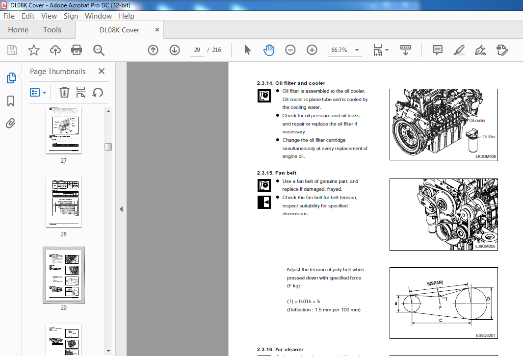
2.3.14. Oil filter and cooler……………………………………. 29
2.3.15. Fan belt……………………………………………….. 29
2.3.16. Air cleaner…………………………………………….. 29
2.3.17. Fuel filter…………………………………………….. 30
2.3.18. Breather oil seperator filter…………………………….. 30
2.3.19. Fuel requirements……………………………………….. 31
2.3.20. How to select fuel oil…………………………………… 31
2.3.21. Inter cooler……………………………………………. 32
2.3.22. Turbo charger…………………………………………… 33
2.3.23. Cooling system………………………………………….. 34
2.3.24. Coolant pressure cap…………………………………….. 35
2.3.25. Cooling water…………………………………………… 36
2.3.26. Valve clearance adjust procedure………………………….. 38
2.3.27. Cylinder compression pressure…………………………….. 40
2.3.28. Battery………………………………………………… 41
2.3.29. Starting motor………………………………………….. 42
2.4. Diagnosis and Remedy…………………………………………… 43
2.5. Engine Inspection……………………………………………… 53
2.5.1. Stopping engine………………………………………….. 53
2.5.3. Use of original parts for repair and replacement…………….. 54
3. Disassembly and Reassembly of Major Components…………………………. 55
3.1. Engine Disassembly…………………………………………….. 55
3.1.1. General precautions………………………………………. 55
3.1.2. Cooling water……………………………………………. 55
3.1.3. Oil level gauge………………………………………….. 55
3.1.4. Engine oil………………………………………………. 56
3.1.5. Inter cooler…………………………………………….. 56
3.1.6. Cooling fan……………………………………………… 56
3.1.7. Belt……………………………………………………. 56
3.1.8. Alternator………………………………………………. 57
3.1.9. Breather………………………………………………… 57
3.1.10. Air pipe and air heater………………………………….. 57
3.1.11. Fuel filter…………………………………………….. 58
3.1.12. Intake manifold…………………………………………. 58
3.1.13. Common rail and high pressure pipe………………………… 58
3.1.14. Fuel high pressure pump………………………………….. 59
3.1.15. EGR valve………………………………………………. 59
3.1.16. EGR cooler……………………………………………… 60
3.1.17. HC dosing injection (HC : hydro-carbon)……………………. 60
3.1.18. HC dosing metering unit………………………………….. 61
3.1.19. Turbo charger…………………………………………… 61
3.1.20. Exhaust manifold………………………………………… 61
3.1.21. Air con. compressor……………………………………… 61
3.1.22. Cooling water pipe………………………………………. 62
3.1.23. Cooling water pump………………………………………. 62
3.1.24. Starting motor………………………………………….. 63
3.1.25. Oil filter……………………………………………… 63
3.1.26. Vibration damper………………………………………… 63
3.1.27. Cylinder head cover……………………………………… 64
3.1.28. Rocker arm……………………………………………… 64
3.1.29. Injector……………………………………………….. 65
3.1.30. Cylinder head…………………………………………… 65
3.1.31. Valve and valve stem seal………………………………… 66
3.1.32. Lifting hook……………………………………………. 66
3.1.33. Oil cooler……………………………………………… 66
3.1.34. Oil pan………………………………………………… 67
3.1.35. Front oil seal cover…………………………………….. 67
3.1.36. Oil pump & pipe…………………………………………. 67
3.1.37. Fly wheel………………………………………………. 67
3.1.38. Flywheel housing………………………………………… 68
3.1.39. Cam gear and idle gear…………………………………… 68
3.1.40. Timing gear case………………………………………… 68
3.1.41. Piston & connecting-rod………………………………….. 69
3.1.42. Bearing cap…………………………………………….. 70
3.1.43. Crankshaft……………………………………………… 70
3.1.44. Oil spray nozzle………………………………………… 71
3.1.45. Camshaft and tappet……………………………………… 71
3.1.46. Cylinder liner………………………………………….. 71
3.2. Inspection and Measurement on Major Parts………………………… 72
3.2.1. Cylinder block…………………………………………… 72
3.2.2. Cylinder head……………………………………………. 72
3.2.3. Inspection of valve and valve guide………………………… 74
3.2.4. Rocker arm………………………………………………. 78
3.2.5. Camshaft………………………………………………… 82
3.2.6. Crankshaft………………………………………………. 84
3.2.7. Piston assembly………………………………………….. 89
3.2.8. Injector projection………………………………………. 93
3.3. Engine Reassembly……………………………………………… 94
3.3.1. General precautions………………………………………. 94
3.3.2. Cylinder block…………………………………………… 94
3.3.3. Cylinder liner…………………………………………… 94
3.3.4. Oil spray nozzle…………………………………………. 94
3.3.5. Crankshaft………………………………………………. 95
3.3.6. Tappet and camshaft………………………………………. 97
3.3.7. Timing gear case…………………………………………. 97
3.3.8. Fuel high pressure and air compressor idle gear……………… 98
3.3.9. Flywheel housing…………………………………………. 99
3.3.10. Oil seal (Rear side)…………………………………….. 99
3.3.11. Fly wheel……………………………………………….100
3.3.12. Piston and connecting rod…………………………………101
3.3.13. Oil pump and oil pipe…………………………………….103
3.3.14. Oil seal………………………………………………..103
3.3.15. Oil pan…………………………………………………104
3.3.16. Crankshaft pulley and vibration damper……………………..105
3.3.17. Intake and exhaust valves…………………………………105
3.3.18. Cylinder head……………………………………………106
3.3.19. Injector………………………………………………..107
3.3.20. Intermediate cover……………………………………….109
3.3.21. Rocker arm………………………………………………110
3.3.22. Cylinder head cover………………………………………110
3.3.23. Oil cooler and oil filter…………………………………111
3.3.24. Cooler water pump………………………………………..111
3.3.25. Starting motor…………………………………………..112
3.3.26. Fuel high pressure pump…………………………………..112
3.3.27. Common rail and high pressure pipe…………………………113
3.3.28. Intake manifold………………………………………….113
3.3.29. Exhaust manifold…………………………………………113
3.3.30. Turbo charger……………………………………………114
3.3.31. Cooling water pipe & thermostat……………………………114
3.3.32. HC dosing injection (HC hydro-carbon)………………………115
3.3.33. HC dosing metering unit…………………………………..115
3.3.34. EGR cooler………………………………………………116
3.3.35. EGR valve……………………………………………….116
3.3.36. Electric control unit : ECU……………………………….117
3.3.37. Crankshaft speed sensor…………………………………..117
3.3.38. Camshaft speed sensorS……………………………………117
3.3.39. Fuel filter……………………………………………..118
3.3.40. Alternator and belt………………………………………118
3.3.41. Air pipe and air heater…………………………………..118
3.3.42. Cooling fan……………………………………………..119
3.3.43. Oil level gauge………………………………………….119
3.3.44. Others………………………………………………….119
3.4. Fuel Injection System…………………………………………..120
3.4.1. Common rail fuel-injection system…………………………..120
3.4.2. Major components of the common rail system…………………..121
3.4.3. Injection characteristics with common rail…………………..122
3.4.4. Fuel high pressure pump……………………………………123
3.4.5. Fuel system………………………………………………123
3.4.6. Fuel tank………………………………………………..123
3.4.7. Fuel delivery pump………………………………………..123
3.4.8. Fuel filter………………………………………………124
3.4.9. High pressure fuel delivery………………………………..124
3.4.10. High pressure system components……………………………124
3.4.11. Construction of the fuel high pressure pump…………………125
3.4.12. Pressure limiter valve……………………………………128
3.4.13. Injector………………………………………………..128
3.4.14. Crankshaft speed sensor…………………………………..131
3.4.15. Camshaft speed sensor…………………………………….131
3.4.16. Accelerator pedal sensor………………………………….132
3.4.17. Boost pressure and temperature sensor………………………132
3.4.18. Engine oil pressure and temperature sensor………………….132
3.4.19. Engine coolant temperature sensor………………………….132
3.5. Electrical System………………………………………………133
3.5.1. Electrical parts………………………………………….133
3.5.2. Harness of electric control unit……………………………134
3.5.3. Connector of electric control unit (ECU)…………………….136
3.5.4. Electric control unit……………………………………..137
3.5.5. Engine harness-1………………………………………….140
3.6. Exhaust Gas Reduction System…………………………………….142
3.6.1. Tier 4 interim exhaust gas reduction device………………….142
3.6.2. Exhaust gas reduction system circuit diagram…………………143
3.6.3. Diesel oxidation catalyst : DOC…………………………….144
3.6.4. Diesel particulate filter : DPF…………………………….145
3.6.5. Instruction to DOC/DPF muffler installation and disassembly……149
3.6.6. HC dosing metering unit, MU………………………………..151
3.6.7. HC dosing injection unit, IU……………………………….153
3.6.8. EGR system……………………………………………….154
3.6.9. EGR cooler……………………………………………….156
3.6.10. EGR system installation and disassembly…………………….156
3.6.11. EGR cooler installation and disassembly…………………….156
3.6.12. Exhaust gas tempature sensor………………………………157
3.6.13. Error code of DPF & EGR…………………………………..159
3.6.14. Caution while working at DPF assembly………………………160
3.7. Engine Diagnostic………………………………………………161
3.7.1. Method of confirmation for the fault code……………………161
3.7.2. Engine fault code and occurring condition……………………161
3.7.3. Input and output of the ECU………………………………..165
3.8. Operating Condition of the ECU…………………………………..166
3.8.1. Engine starting…………………………………………..166
3.8.2. Vehicle running…………………………………………..166
3.8.3. Engine idle adjusting……………………………………..166
3.8.4. Limp home function………………………………………..166
3.8.5. Diagnostic……………………………………………….167
3.8.6. Vehicle operating record…………………………………..167
4. Commissioning and Operation…………………………………………..168
4.1. Preparations…………………………………………………..168
4.2. Breaking-In……………………………………………………168
4.2.1. Operation of a new engine (Break-in)………………………..168
4.2.2. Check points for break-in………………………………….169
4.2.3. Operating after break-In…………………………………..170
4.3. Inspections after Starting………………………………………170
4.3.1. Pressure of lubricating oil………………………………..170
4.3.2. Temperature of cooling water……………………………….170
4.3.3. Over-speed control………………………………………..170
4.4. Operation in Winter Time………………………………………..171
4.4.1. Operation in winter time…………………………………..171
4.4.2. Prevention against freezing of cooling water…………………172
4.4.3. Prevention against excessive cooling………………………..172
4.4.4. Lubricating oil…………………………………………..172
4.5. Engine Components Check after Long Time Running……………………173
4.6. Maintenance and Care……………………………………………173
4.6.1. Periodical Inspection and Maintenance……………………….173
4.6.2. Exchanging of lubrication oil………………………………173
4.6.3. Oil level gauge…………………………………………..174
4.6.4. Oil exchange procedure…………………………………….174
4.6.5. Replacement of oil filter cartridge…………………………175
4.7. Cooling System…………………………………………………176
4.7.1. Coolant draining………………………………………….176
4.7.2. Cleaning of the cooling inside system circuit………………..177
4.8. Adjustment of Valve Clearance……………………………………178
4.8.1. General information……………………………………….178
4.8.2. Valve clearance adjust procedure……………………………178
4.9. Tightening the Cylinder Head Bolts……………………………….180
5. Maintenance of Major Components……………………………………….181
5.1. Cooling System…………………………………………………181
5.1.1. General descriptions and main data………………………….181
5.1.2. Specification…………………………………………….182
5.1.3. Thermostat……………………………………………….182
5.1.4. Diagnostics and troubleshooting…………………………….184
5.2. Lubrication System……………………………………………..185
5.2.1. General descriptions and main data………………………….185
5.2.2. Oil pump…………………………………………………185
5.2.3. Diagnostics and troubleshooting…………………………….187
5.3. Turbo Charger………………………………………………….188
5.3.1. Specification and construction……………………………..188
5.3.2. General information……………………………………….190
5.3.3. Function…………………………………………………191
5.3.4. How to handle the engine…………………………………..192
5.3.5. Routine inspection and maintenance………………………….193
5.3.6. Periodical servicing………………………………………194
5.3.7. Diagnostics and troubleshooting…………………………….196
5.3.8. Structure and exchange of VGT actuator………………………197
5.4. Air Cleaner……………………………………………………198
5.4.1. Maintenance of air cleaner (Only when engine is switched off)….198
5.4.2. Changing air cleaner element……………………………….198
5.4.3. Cleaning air cleaner elements………………………………199
5.5. Belt………………………………………………………….200
6. Special Tool List……………………………………………………202
Appendix………………………………………………………………205
1. Engine assembly DL08K…………………………………………….216
VIDEO PREVIEW OF THE MANUAL:

IMAGES PREVIEW OF THE MANUAL:


PLEASE NOTE:
- This is the SAME exact manual used by your dealers to fix your vehicle.
- The same can be yours in the next 2-3 mins as you will be directed to the download page immediately after paying for the manual.
- Any queries / doubts regarding your purchase, please feel free to contact [email protected]
R.D


Xzavier Avery –
Very efficient