

DEUTZ-FAHR Agrofarm 85 Agrofarm 100 Workshop Manual – PDF DOWNLOAD
FILE DETAILS:
DEUTZ-FAHR Agrofarm 85 Agrofarm 100 Workshop Manual – PDF DOWNLOAD
Language : English
Pages : 715
Downloadable : Yes
File Type : PDF
Size: 67.6 MB
IMAGES PREVIEW OF THE MANUAL:
VIDEO PREVIEW OF THE MANUAL:
DESCRIPTION:
DEUTZ-FAHR Agrofarm 85 Agrofarm 100 Workshop Manual – PDF DOWNLOAD
INTRODUCTION:
The purpose of this workshop manual is to provide instruction for repair technicians and a practical guide to improving the quality of repairs. This manual enables repair technicians to acquire a thorough knowledge of the machine, indicating the correct methods for fault diagnosis, for working in safety and for accurate dimensional checks and visual inspections.
- The instructions also indicate the products to use, the tightening torques and the adjustment data. The technical material contained in this manual is reserved to Authorised Dealers and Service Centres who will be duly informed of any technical changes to the machines in question through the issue of documents regarding modifi cations, updates and supplements for optional equipment.
- All technicians and their colleagues are expressly forbidden from reproducing any part of this manual in any form or from communicating the contents to third parties without the express written permission of the Manufacturer, who remains the sole owner of this document with all rights reserved in accordance with applicable laws.
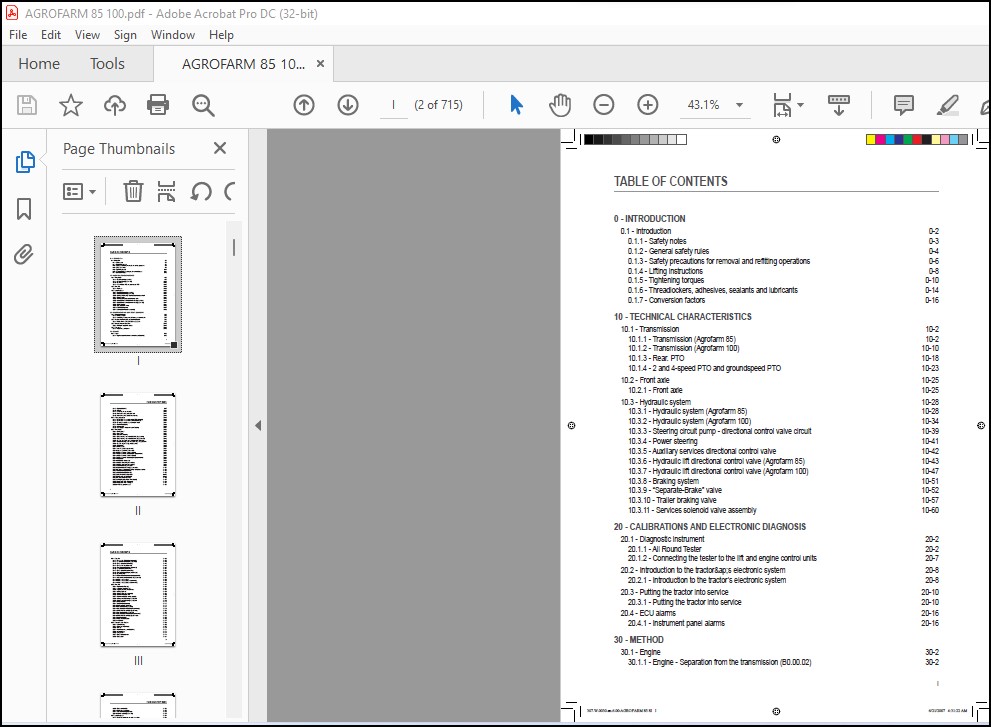
TABLE OF CONTENTS:
DEUTZ-FAHR Agrofarm 85 Agrofarm 100 Workshop Manual – PDF DOWNLOAD
0 – INTRODUCTION
0.1 – Introduction 0-2
0.1.1 – Safety notes 0-3
0.1.2 – General safety rules 0-4
0.1.3 – Safety precautions for removal and refi tting operations 0-6
0.1.4 – Lifting instructions 0-8
0.1.5 – Tightening torques 0-10
0.1.6 – Threadlockers, adhesives, sealants and lubricants 0-14
0.1.7 – Conversion factors 0-16
10 – TECHNICAL CHARACTERISTICS
10.1 – Transmission 10-2
10.1.1 – Transmission (Agrofarm 85) 10-2
10.1.2 – Transmission (Agrofarm 100) 10-10
10.1.3 – Rear. PTO 10-18
10.1.4 – 2 and 4-speed PTO and groundspeed PTO 10-23
10.2 – Front axle 10-25
10.2.1 – Front axle 10-25
10.3 – Hydraulic system 10-28
10.3.1 – Hydraulic system (Agrofarm 85) 10-28
10.3.2 – Hydraulic system (Agrofarm 100) 10-34
10.3.3 – Steering circuit pump – directional control valve circuit 10-39
10.3.4 – Power steering 10-41
10.3.5 – Auxiliary services directional control valve 10-42
10.3.6 – Hydraulic lift directional control valve (Agrofarm 85) 10-43
10.3.7 – Hydraulic lift directional control valve (Agrofarm 100) 10-47
10.3.8 – Braking system 10-51
10.3.9 – “Separate-Brake” valve 10-52
10.3.10 – Trailer braking valve 10-57
10.3.11 – Services solenoid valve assembly 10-60
20 – CALIBRATIONS AND ELECTRONIC DIAGNOSIS
20.1 – Diagnostic instrument 20-2
20.1.1 – All Round Tester 20-2
20.1.2 – Connecting the tester to the lift and engine control units 20-7
20.2 – Introduction to the tractor≈s electronic system 20-8
20.2.1 – Introduction to the tractor’s electronic system 20-8
20.3 – Putting the tractor into service 20-10
20.3.1 – Putting the tractor into service 20-10
20.4 – ECU alarms 20-16
20.4.1 – Instrument panel alarms 20-16
30 – METHOD
30.1 – Engine 30-2
30.1.1 – Engine – Separation from the transmission (B0.00.02) 30-2
307.W.0030.en.6.00-AGROFARM 85 8I I 6/21/2007 4:31:22 AM
TABLE OF CONTENTS
II
30.1.2 – Engine (B0.00.01) 30-7
30.1.3 – Fan belt 30-12
30.1.4 – Tensioning the fan drive belt 30-13
30.1.5 – Alternator and fuel pump drive belt 30-14
30.1.6 – Alternator and fuel pump belt tensioning 30-15
30.2 – Engine accessories 30-16
30.2.1 – RADIATOR – Tractor without front PTO (C0.01.01) 30-16
30.2.2 – RADIATOR – Tractor with front PTO (C0.01.01) 30-20
30.2.3 – Changing the coolant and fl ushing the circuit 30-24
30.2.4 – Fuel tank (C0.03.01) 30-26
30.2.5 – Starter motor 30-29
30.2.6 – Exhaust pipe – Tractor with cab (C0.06.01) 30-31
30.3 – Transmission 30-32
30.3.1 – Parking brake 30-32
30.3.2 – Clutch plate 30-34
30.3.3 – Clutch thrust bearing 30-36
30.3.4 – Clutch housing – assembly (D0.02.01) (Agrofarm 85) 30-37
30.3.5 – Clutch housing – assembly (D0.02.01) (Agrofarm 100) 30-42
30.3.6 – Gearbox and shuttle assy. – complete unit (D0.09.03) 30-47
30.3.7 – Disassembly of gearbox and shuttle assy. – complete unit 30-49
30.3.8 – Gearbox support and gear selector rods 30-53
30.3.9 – Shuttle shaft 30-56
30.3.10 – Primary shaft 30-60
30.3.11 – Secondary shaft (Agrofarm 85) 30-61
30.3.12 – Secondary shaft (Agrofarm 100) 30-66
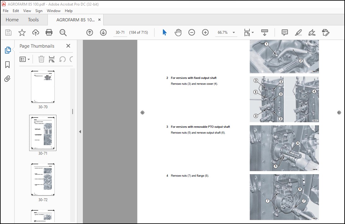
30.3.13 – PTO output shaft (4 speed version) 30-71
30.3.14 – PTO output shaft disassembly (4 speed version) 30-74
30.3.15 – PTO output shaft (2 speed version) 30-77
30.3.16 – PTO output shaft disassembly (2 speed versions) 30-80
30.3.17 – PTO clutch 30-81
30.3.18 – PTO clutch disassembly 30-85
30.3.19 – PTO fi nal shaft (2-speed version) 30-90
30.3.20 – PTO fi nal shaft (4-speed version) 30-94
30.3.21 – Groundspeed PTO fi nal shaft 30-98
30.3.22 – Groundspeed PTO engagement device 30-101
30.3.23 – Range and differential assembly – complete assembly 30-102
30.3.24 – Rear pinion (Agrofarm 85) 30-103
30.3.25 – Rear pinion (Agrofarm 100) 30-108
30.3.26 – Four-wheel drive output shaft 30-113
30.3.27 – Differential – Bevel gear pair 30-116
30.3.28 – Range selector assembly 30-125
30.3.29 – Changing transmission oil (D0.00.01) 30-127
30.3.30 – Pump drive PTO – Outer gear 30-129
30.3.31 – Pump drive PTO – Inner gear 30-131
30.3.32 – 4WD engagement device 30-133
307.W.0030.en.6.00-AGROFARM 85 8II II 6/21/2007 4:31:22 AM
TABLE OF CONTENTS
III
30.4 – Rear axle 30-136
30.4.1 – RH rear axle (E0.02.01) (Agrofarm 85) 30-136
30.4.2 – LH rear axle (E0.02.02) (Agrofarm 85) 30-139
30.4.3 – RH/LH rear axle (Agrofarm 85) 30-143
30.4.4 – RH rear axle (Agrofarm 100) 30-148
30.4.5 – Planet carrier assembly (Agrofarm 85) 30-152
30.4.6 – LH rear axle (Agrofarm 100) 30-154
30.4.7 – RH/LH rear axle (Agrofarm 100) 30-158
30.4.8 – Planet carrier assembly (Agrofarm 100) 30-164
30.4.9 – Rear differential 30-166
30.4.10 – Rear differential disassembly (Agrofarm 85) 30-169
30.4.11 – Rear differential disassembly (Agrofarm 100) 30-172
30.4.12 – Rear axle brake discs 30-175
30.4.13 – Rear axle brake piston (Agrofarm 85) 30-176
30.4.14 – Rear axle brake piston (Agrofarm 100) 30-178
30.5 – Front axle 30-180
30.5.1 – Front carrier (F0.01.01) 30-180
30.5.2 – 4WD front axle (F0.03.01) 30-184
30.5.3 – Adjusting the front axle end fl oat 30-186
30.5.4 – Steering cylinders 30-189
30.5.5 – Steering cylinders disassembly 30-191
30.5.6 – Final drive reduction unit 30-195
30.5.7 – Final drive reduction unit disassembly 30-197
30.5.8 – Steering knuckle housing and halfshaft 30-203
30.5.9 – Steering knuckle housing and halfshaft 30-209
30.5.10 – Differential unit 30-212
30.5.11 – Differential disassembly 30-214
30.5.12 – Differential unit adjustment 30-217
30.5.13 – Bevel gear pair (Agrofarm 85) 30-221
30.5.14 – Bevel gear pair disassembly (Agrofarm 85) 30-226
30.5.15 – Differential disassembly (Agrofarm 85) 30-236
30.5.16 – Bevel gear pair (Agrofarm 100) 30-238
30.5.17 – Bevel gear pair disassembly (Agrofarm 100) 30-243
30.5.18 – Differential disassembly (Agrofarm 100) 30-253
30.5.19 – Front brake discs 30-255
30.5.20 – Front axle brake piston 30-256
30.5.21 – 4WD shaft 30-257
30.6 – Bodywork – Cab – Platform 30-260
30.6.1 – Cab (G0.03.01) 30-260
30.6.2 – Front hoods (G0.01.01) 30-268
30.6.3 – Fenders 30-270
30.6.4 – Front instrument panel (G0.06.04) 30-271
30.6.5 – Air conditioning 30-274
30.6.6 – Compressor 30-277
30.6.7 – Clutch master cylinder 30-278
30.6.8 – Clutch piston 30-281
307.W.0030.en.6.00-AGROFARM 85 8III III 6/21/2007 4:31:23 AM
TABLE OF CONTENTS
IV
30.6.9 – Clutch control circuit 30-282
30.6.10 – Brake master cylinders 30-283
30.6.11 – Control levers (Agrofarm 85) 30-285
30.6.12 – Control levers (Agrofarm 100) 30-289
30.7 – Hydraulic system 30-294
30.7.1 – Pump for hydraulic lift and auxiliary services 30-294
30.7.2 – Power steering (H0.02.01) 30-296
30.7.3 – Pressure relief valve setting: 30-298
30.7.4 – Power steering disassembly 30-299
30.7.5 – Power steering pump 30-316
30.7.6 – Rear 4-way auxiliary services control valve (Agrofarm 85) 30-318
30.7.7 – Rear 6-way auxiliary services control valve (Agrofarm 100) 30-320
30.7.8 – Braking circuit (Agrofarm 85) 30-324
30.7.9 – Braking circuit (Agrofarm 100) 30-326
30.7.10 – Services solenoid valve assembly 30-329
30.8 – Front PTO 30-331
30.8.1 – Front PTO 30-331
30.8.2 – PTO assembly. 30-336
30.8.3 – Pump assy 30-347
30.8.4 – Clutch-brake assembly 30-349
30.8.5 – Solenoid valve assy 30-356
30.9 – Front lift 30-357
30.9.1 – Front lift 30-357
30.9.2 – Lift cylinders 30-359
30.10 – Rear lift 30-363
30.10.1 – Lift – Complete assembly (R0.02.03) (Agrofarm 85) 30-363
30.10.2 – Lift disassembly – complete assembly (Agrofarm 85) 30-366
30.10.3 – Lift – Complete assembly (R0.02.03) (Agrofarm 100) 30-371
30.10.4 – Lift disassembly – Complete assembly (Agrofarm 100) 30-375
30.10.5 – Lift cylinder (Agrofarm 100) 30-380
30.10.6 – Bushes (Agrofarm 100) 30-382
30.10.7 – Hydraulic lift directional control valve (Agrofarm 85) 30-383
30.10.8 – Lift control valve disassembly (Agrofarm 85) 30-384
30.10.9 – Lift control valve disassembly (Agrofarm 100) 30-390
30.10.10 – Mechanical draft sensor (Agrofarm 85) 30-396
30.10.11 – Mechanical draft sensor disassembly (Agrofarm 85) 30-397
30.10.12 – Mechanical draft sensor (Agrofarm 100) 30-399
30.10.13 – Mechanical draft sensor disassembly (Agrofarm 100) 30-400
30.10.14 – 3-point linkage 30-402
30.11 – Wheels 30-404
30.11.1 – Front wheels (S0.01.01) 30-404
30.11.2 – Rear wheels (S0.02.01) 30-405
30.12 – Ballast – Towing hitches 30-406
30.12.1 – Towing hitch slide (Agrofarm 85) 30-406
30.12.2 – Towing hitch slide (Agrofarm 100) 30-407
307.W.0030.en.6.00-AGROFARM 85 8IV IV 6/21/2007 4:31:23 AM
TABLE OF CONTENTS
V
40 – WIRING DIAGRAMS
40.1 – Introduction 40-2
40.1.1 – Structure of the unit 40-2
40.1.2 – Wiring and components index 40-8
40.2 – Components 40-22
40.2.1 – Components 40-22
40.3 – Systems 40-33
40.3.1 – Earthing points 40-33
40.3.2 – Starting and pre-heating 40-35
40.3.3 – Lights selector – Tractor with cab 40-37
40.3.4 – Lights selector – Tractor with platform 40-39
40.3.5 – Diagnostic accessories – Tractor with standard cab 40-41
40.3.6 – Diagnostic accessories – Tractor with high-visibility cab 40-43
40.3.7 – Instrument panel 40-45
40.3.8 – Worklights – Tractor with standard cab 40-47
40.3.9 – Wipers – Tractor with standard cab 40-49
40.3.10 – Heating system – Tractor with standard cab 40-51
40.3.11 – Air conditioning system – Tractor with standard cab 40-53
40.3.12 – Worklights – Tractor with high-visibility cab 40-55
40.3.13 – Wipers – Tractor with high-visibility cab 40-57
40.3.14 – Heating system – Tractor with high-visibility cab 40-59
40.3.15 – Air conditioning system – Tractor with high-visibility cab 40-61
40.3.16 – Transmission 40-63
40.3.17 – PTO 40-65
40.3.18 – Brakes 40-67
40.3.19 – CAN BUS ELECTRONIC SYSTEM 40-69
40.4 – Wiring looms 40-70
40.4.1 – Hood lights wiring – 0.014.8107.4/20 40-70
40.4.2 – Hood lights wiring connector positions 40-71
40.4.3 – Engine wiring – version with front battery – 0.014.8629.4/20 40-73
40.4.4 – Engine wiring connector positions – version with front battery 40-74
40.4.5 – Engine wiring – version with lateral battery – 0.015.1597.4/10 40-77
40.4.6 – Engine wiring connector positions – version with lateral battery 40-78
40.4.7 – Battery wiring loom – 0.014.8806.4/20 40-81
40.4.8 – Battery wiring connector positions 40-82
40.4.9 – Preheating wiring loom – 0.014.9195.4/20 40-86
40.4.10 – Pre-heating wiring connector positions 40-87
40.4.11 – Power supply wiring – 0.015.1983.4/10 40-89
40.4.12 – Power supply wiring connector positions 40-90
40.4.13 – Instrument panel wiring – 0.014.8628.4/20 40-93
40.4.14 – Instrument panel wiring connector positions 40-97
40.4.15 – RH drivetrain wiring – 0.014.8630.4/20 40-101
40.4.16 – RH drivetrain wiring connector positions 40-102
40.4.17 – LH drivetrain wiring – 0.014.9193.4/20 40-104
40.4.18 – LH drivetrain wiring connector positions 40-105
307.W.0030.en.6.00-AGROFARM 85 8V V 6/21/2007 4:31:23 AM
TABLE OF CONTENTS
VI
40.4.19 – Power supply wiring – Tractor with standard cab – 0.014.9375.4/20 40-107
40.4.20 – Power supply wiring connector positions – Tractor with standard cab 40-108
40.4.21 – Roof line wiring – Tractor with standard cab – 0.009.7850.4/50 40-110
40.4.22 – Roof line wiring connector positions – Tractor with standard cab 40-112
40.4.23 – Heating wiring – Tractor with standard cab – 0.010.2147.2 40-115
40.4.24 – Heating system wiring connector positions – Tractor with standard cab 40-116
40.4.25 – Air conditioning wiring – Tractor with standard cab – 0.010.2153.2 40-118
40.4.26 – Air conditioner wiring connector positions – Tractor with standard cab 40-119
40.4.27 – Air conditioning cooler fan wiring – Tractor with standard cab – 0.009.7853.3/20 40-121
40.4.28 – Air conditioner exchanger fan wiring connector positions – Tractor with standard cab 40-122
40.4.29 – Front-rear worklights wiring – Tractor with standard cab – 0.009.7851.4/50 40-124
40.4.30 – Supplementary worklights wiring connector positions – Tractor with standard cab 40-126
40.4.31 – Supplementary worklights wiring – Tractor with standard cab – 0.015.1435.4/10 40-128
40.4.32 – Supplementary worklights wiring connector positions – Tractor with standard cab 40-130
40.4.33 – Windscreen wiper wiring – Tractor with standard cab – 0.010.4516.3 40-132
40.4.34 – Windscreen wiper connector positions wiring – Tractor with standard cab 40-133
40.4.35 – Loudspeaker wiring – Tractor with standard cab – 0.011.0729.4/10 40-135
40.4.36 – Loudspeaker wiring connector positions – Tractor with standard cab 40-137
40.4.37 – Cab power supply wiring – Tractor with high-visibility cab – 0.014.9376.4/10 40-139
40.4.38 – Cab power supply wiring connector positions – Tractor with high-visibility cab 40-140
40.4.39 – Roof line wiring – Tractor with high-visibility cab – 0.011.3606.4/50 40-142
40.4.40 – Roof line wiring connector positions – Tractor with high-visibility cab 40-145
40.4.41 – Heating system wiring – Tractor with high-visibility cab – 0.010.2554.2 40-147
40.4.42 – Heating system wiring connector positions – Tractor with high-visibility cab 40-149
40.4.43 – Air conditioning wiring – Tractor with high-visibility cab – 0.010.2560.0 40-151
40.4.44 – Air conditioner wiring connector positions – Tractor with high-visibility cab 40-153
40.4.45 – Air conditioning cooler fan wiring – Tractor with high-visibility cab – 0.011.3610.3/20 40-155
40.4.46 – Air conditioning exchanger fan wiring connector positions – Tractor with high-visibility
cab 40-156
40.4.47 – Front-rear worklights wiring – Tractor with high-visibility cab – 0.011.3595.3/10 40-158
40.4.48 – Worklights wiring connector positions – Tractor with high-visibility cab 40-159
40.4.49 – Supplementary worklights wiring – Tractor with high-visibility cab – 0.015.1437.4/10 40-161
40.4.50 – Supplementary worklights wiring connector positions – Tractor with high-visibility cab 40-162
40.4.51 – Windscreen wiper wiring – Tractor with high-visibility cab – 0.011.3597.3 40-166
40.4.52 – Windscreen wiper wiring connector positions – Tractor with high-visibility cab 40-167
40.4.53 – Loudspeaker, radio, rear wiper, fl ashing light and clock wiring – Tractor with highvisibility
cab – 0.011.3596.3/40 40-169
40.4.54 – Loudspeaker, radio, rear wiper, fl ashing light and clock wiring connector positions
– Tractor with high-visibility cab 40-171
40.4.55 – Wiring for front lights – Tractor with cab – 0.010.8189.3/40 40-173
40.4.56 – Front lights wiring connector positions – Tractor with cab 40-174
40.4.57 – Wiring for lower front lights – Tractor with cab – 0441.1923.4 40-177
40.4.58 – Lower front lights wiring connector positions – Tractor with cab 40-178
40.4.59 – Wiring for front lights – Tractor with platform – 0.015.3094.4 40-180
40.4.60 – Front lights wiring connector positions – Tractor with platform 40-182
40.4.61 – Worklights wiring – Tractor with platform – 0.014.9281.4 40-184
307.W.0030.en.6.00-AGROFARM 85 8VI VI 6/21/2007 4:31:23 AM
TABLE OF CONTENTS
VII
40.4.62 – Worklights wiring connector positions – Tractor with platform 40-186
40.4.63 – Rotating beacon wiring – 0.012.9909.4 40-188
40.4.64 – Position of rotary beacon wiring connectors 40-189
40.4.65 – Trailer hydraulic braking wiring – 0.014.1645.4/10 40-191
40.4.66 – Trailer hydraulic braking wiring connector positions 40-192
PLEASE NOTE:
- This is the same manual used by the dealers to diagnose and troubleshoot your vehicle
- You will be directed to the download page as soon as the purchase is completed. The whole payment and downloading process will take anywhere between 2-5 minutes
- Need any other service / repair / parts manual, please feel free to contact [email protected] . We still have 50,000 manuals unlisted
S.V


