

 (1)")
 (3)")
 (2)")
Case 1085C Excavator Service Repair Manual (8-14930) Case 1085C
VIDEO PREVIEW:

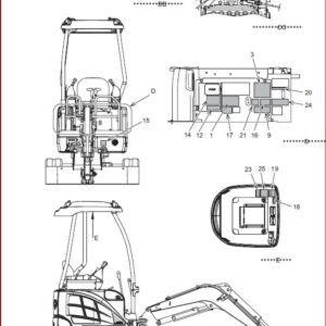
IMAGE PREVIEW:
GENERAL INFORMATION:
Case 1085C Excavator Service Repair Manual (8-14930) Case 1085C
- The fuel injectors are in the cylinder head. There is one injector for each cylinder. The fuel injector sends a measured amount of fuel to the combus- tion chamber from the injection pump. Each quan- tity of fuel must be sent to the combustion cham- ber in the form of fine particles. This will make sure that there is complete combustion and efficient engine performance.
- The injector tip end and the injector valve are a matched assembly. The two parts are made smooth to lit together with accuracy. The injector tip or the injector valve can not be replaced separately lor service. I! it is necessary to replace either the valve or tip, replace the complete tlp assembly.
- Do not mix tip assemblies and bed- ies while the injectors are being disassembled.
- INJECTOR BODY — The body holds the injector parts in the correct position in the cylinder head. The body has a high pressure channel and a leak off channel. The lower face of the body has a fin- ished surface and has two holes in the surface for locating dowel pins.
- INJECTOR VALVE – The valve controls the flow of the fuel from the injector.
- VALVE TOP – The valve step has two dowel pins which hold the valve tip to the body. This will make a spray pattern that is correct Both laces ol the valve slop have a line surface finish. The valve stop controls the distance that the valve will move.
- OPENING PRESSURE CONTROL SPRING – The spring controls the fuel pressure that is necessary to lift the valve from the seat. SHIMS – The shims push down on the spring to keep a given pressure on the valve.
- lNJECTOR TIP – The valve and the valve seat are in the injector tip. There are orifices In the injectortip that atomize the fuel for better combustion and separate the fuel spray to mix the fuel spray with air.
TABLE OF CONTENTS:
Case 1085C Excavator Service Repair Manual (8-14930) Case 1085C
1 GENERAL
Section Index – General
Standard Torque Specrfrcattons
Detailed Engine Spectficattons
2 ENGINES
Section Index – Engines
Engine and Radiator Removal and Installation
Stall Tests
Cylinder Head and Valve Trarn
Cylinder Block. Pistons. Rods. Camshaft. Main Bearings. Oil Seals. and Flywheel .
Lubrication System
Cooling System
Turbocharger
Turbocharger Failure Analysis
3 FUEL SYSTEM
Section Index – Fuel System
Removal and Installation of Master Cylinder and Accelerator Cylinder
Accelerator Master mltnder
Accelerator Cylinder
Fuel system and Filters
Pump Drive Gear. Timing Pin, Fuel Shutoft Solenoid. Primer Pump, and Pump Timir
Fuel Injectors
4 ELECTRICAL SYSTEM
Section Index – Electrical
Removal and Installation of Starter and Alternator
Electrical Specifications. Troubleshooting. and Schematics
Starter and Starter Solenoid
45 Ampere Alternator
Batteries
Electric Swivel
Gauges
5 STEERING
Section Index ~ Steering
Removal and Installation of Components
Steering Specifications. Schematic. and Troubleshooting
Steering Control Valve
Steering Selector Valve
Front Axle
Accumulator
Steering Cylinder
6 POWER TRAIN
Section Index – Power Train
Removal and Installation of Power Train Components
Transmission Specification. Schematic. and Troubleshooting
Torque Converter
Transmrssron
Drive Shafts and Universal Jornts
Differential and Planetary
Wheels and Tires
7 BRAKES
Section Index – Brakes
Removal and Installation of Brake Components
Brake Specifications. Pressure Checks. and Adjustments
Brakes
Parking Brake
Accumulator
Swing Brake
Parking Brake Actuator
8 HYDRAULICS
Section Index – Hydraulics
Removal and Installation of Hydraulic Components
Hydraulic Schematics. Specifications, and Troubleshooting
Cleaning the Hydraulic System
Pump for Boom and Tool
Pump for Ann and Swing
Pump for Steering and Controls
Main Control Valves
Outrigger Control Valves
Remote Control Valves – Hand
Remote Control Valves – Foot
High Speed Valve
Solenoid Valve
Control Circuit Valve
Swing Motor
Swing Relief Valve
Hydraulic Syrivel
Cylinders
9 MOUNTED EQUIPMENT
Section Index – MOunted Equipment
Pedals and Levers
Swing Gearbox
Boom and Arm
Attachments
Turntable Bearing and Related Parts
PLEASE NOTE:
⦁ This is the same manual used by the dealers to diagnose and troubleshoot your vehicle
⦁ You will be directed to the download page as soon as the purchase is completed. The whole payment and downloading process will take anywhere between 2-5 minutes
⦁ Need any other service / repair / parts manual, please feel free to contact [email protected] . We still have 50,000 manuals unlisted


Zeke K –
A little confusing on how to download.