Acer Aspire 1606 Laptop Service Guide Manual – PDF DOWNLOAD
Acer Aspire 1606 Laptop Service Guide Manual – PDF DOWNLOAD
Preface :
Before using this information and the product it supports, please read the following general information.
1. This Service Guide provides you with all technical information relating to the BASIC CONFIGURATION decided for Acer’s “global” product offering. To better fit local market requirements and enhance product competitiveness, your regional office MAY have decided to extend the functionality of a machine (e.g. add-on card, modem, or extra memory capability). These LOCALIZED FEATURES will NOT be covered in this generic service guide. In such cases, please contact your regional offices or the responsible personnel/channel to provide you with further technical details.
2. Please note WHEN ORDERING FRU PARTS, that you should check the most up-to-date information available on your regional web or channel. If, for whatever reason, a part number change is made, it will not be noted in the printed Service Guide. For ACER-AUTHORIZED SERVICE PROVIDERS, your Acer office may have a DIFFERENT part number code to those given in the FRU list of this printed Service Guide. You MUST use the list provided by your regional Acer office to order FRU parts for repair and service of customer machines.
Acer Aspire 1606 Laptop Service Guide Manual – PDF DOWNLOAD
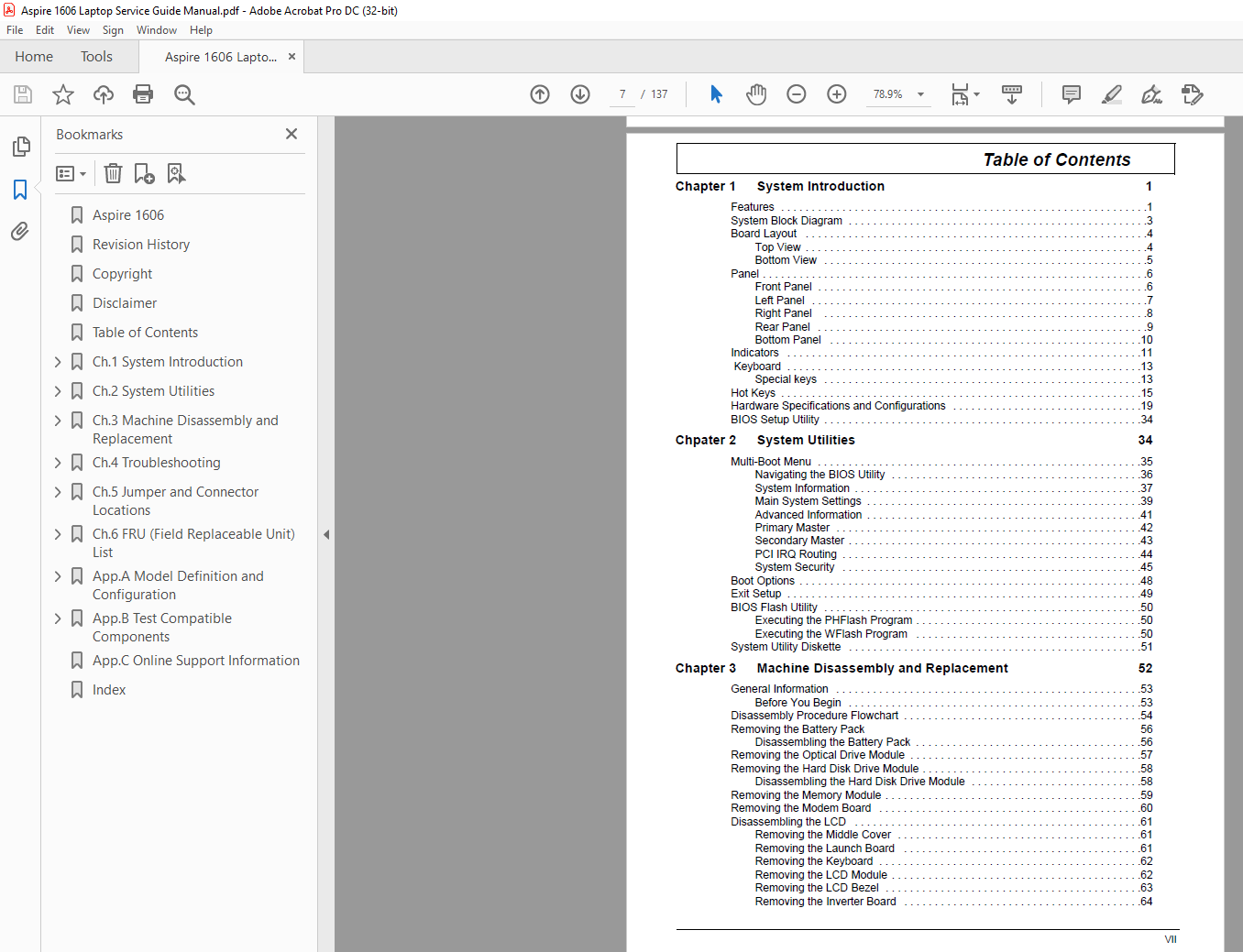
Aspire 1606.........................................  1
Revision History....................................  2
Copyright...........................................  3
Disclaimer..........................................  3
Table of Contents...................................  7
Ch.1 System Introduction............................ 10
	Features........................................ 10
	System Block Diagram............................ 12
	Board Layout.................................... 13
		Top View.................................... 13
		Bottom View................................. 14
	Panel........................................... 15
		Front Panel................................. 15
		Left Panel.................................. 16
		Right Panel................................. 17
		Rear Panel.................................. 18
		Bottom Panel................................ 19
	Indicators...................................... 20
	Keyboard........................................ 22
		Special keys................................ 22
	Hot Keys........................................ 24
	Hardware Specifications and Configurations...... 28
Ch.2 System Utilities............................... 43
	BIOS Setup Utility.............................. 43
	Multi-Boot Menu................................. 44
		Navigating the BIOS Utility................. 45
		System Information.......................... 46
		Main System Settings........................ 48
		Advanced Information........................ 50
		Primary Master.............................. 51
		Secondary Master............................ 52
		PCI IRQ Routing............................. 53
		System Security............................. 54
	Boot Options.................................... 57
	Exit Setup...................................... 58
	BIOS Flash Utility.............................. 59
		Executing the PHFlash Program............... 59
		Executing the WFlash Program................ 59
	System Utility Diskette......................... 60
Ch.3 Machine Disassembly and Replacement............ 61
	General Information............................. 62
		Before You Begin............................ 62
	Disassembly Procedure Flowchart................. 63
	Removing the Battery Pack....................... 65
		Disassembling the Battery Pack.............. 65
	Removing the Optical Drive Module............... 66
	Removing the Hard Disk Drive Module............. 67
		Disassembling the Hard Disk Drive Module.... 67
	Removing the Memory Module...................... 68
	Removing the Modem Board........................ 69
	Disassembling the LCD........................... 70
		Removing the Middle Cover................... 70
		Removing the Launch Board................... 70
		Removing the Keyboard....................... 71
		Removing the LCD Module..................... 71
		Removing the LCD Bezel...................... 72
		Removing the Inverter Board................. 73
		Removing the LCD............................ 74
		Removing the LCD Hinges..................... 74
		Removing the LCD Coaxial Cable.............. 75
	Disassembling the Main Unit..................... 76
		Removing the Keyboard Bracket............... 76
		Removing the DC Charger Plate............... 76
		Removing the RTC Battery.................... 76
		Removing the Touch Pad Frame................ 77
		Removing the DC to DC Board................. 77
		Removing the CPU Fan Sink................... 78
		Removing the Processor...................... 78
		Installing the Processor.................... 78
		Removing the Upper Case..................... 79
		Removing the Touch Pad Board................ 80
		Removing the Touch Pad Button............... 80
		Removing the Touch Pad Scroll Key........... 81
		Removing the Touch Pad FPC.................. 81
		Removing the VGA Thermal Plate.............. 82
		Removing the Floppy Disk Drive Module....... 82
		Removing the Speakers....................... 84
		Removing the Main Board..................... 85
		Removing the PCMCIA Slot.................... 86
		Removing the I/O Port Bracket............... 87
Ch.4 Troubleshooting................................ 89
	System Check Procedures......................... 90
		External Diskette Drive Check............... 90
		External CD-ROM Drive Check................. 90
		Keyboard or Auxiliary Input Device Check.... 91
		Memory Check................................ 91
		Power System Check.......................... 91
		Touchpad Check.............................. 93
	Power-On Self-Test (POST) Error Message......... 94
	Index of Error Messages......................... 95
	POST Codes...................................... 98
	Index of Symptom-to-FRU Error Message...........102
	Intermittent Problems...........................105
	Undetermined Problems...........................106
	Index of Phlash16 Error Message.................107
	Index of PQA Diagnostic Error Code, Message.....109
Ch.5 Jumper and Connector Locations.................111
	Top View........................................111
	Bottom View.....................................113
		CN27 Jumper Settings........................114
Ch.6 FRU (Field Replaceable Unit) List..............115
	Exploded Diagram................................116
App.A Model Definition and Configuration............127
	Model Number Definition.........................127
App.B Test Compatible Components....................129
	Microsoft Windows XP Environment Test...........130
App.C Online Support Information....................133
Index...............................................135