

2008 Yamaha YXR70FX Rhino 700FI Service Repair Manual
FILE DETAILS:
2008 Yamaha YXR70FX Rhino 700FI Service Repair Manual
Language : English
Pages : 516
Downloadable : YES
Format : PDF
Size : 52.7 MB
DESCRIPTION:
2008 Yamaha YXR70FX Rhino 700FI Service Repair Manual
FOREWORD:
This manual was produced by the Yamaha Motor Company primarily for use by Yamaha dealers and their qualified mechanics. It is not possible to include all the knowledge of a mechanic in one manual, so it is assumed that anyone who uses this book to perform maintenance and repairs on Yamaha vehicle has a basic understanding of the mechanical ideas and the procedures of vehicle repair.
- Repairs attempted by anyone without this knowledge are likely to render the vehicle unsafe and unfit for use. This model has been designed and manufactured to perform within certain specifications in regard to performance and emissions.
- Proper service with the correct tools is necessary to ensure that the vehicle will operate as designed. If there is any question about a service procedure, it is imperative that you contact a Yamaha dealer for any service information changes that apply to this model.
- This policy is intended to provide the customer with the most satisfaction from his vehicle and to conform to federal environmental quality objectives. Yamaha Motor Company, Ltd. is continually striving to improve all its models. Modifications and significant changes in specifications or procedures will be forwarded to all authorized Yamaha dealers and will appear in future editions of this manual where applicable.
TABLE OF CONTENTS:
2008 Yamaha YXR70FX Rhino 700FI Service Repair Manual
2008 Rhino Fuel Injection 700FI YXR70FX Service Manual 1
Important 3
Important Information 3
How To Use This Manual 4
Manual Organization 4
Exploded Diagrams 4
Symbols 5
Table Of Contents 7
Chapter 1 General Information 8
General Information 20
Vehicle Identification 20
Vehicle Identification Number 20
Model Label 20
Features 21
Outline Of The FI System 21
FI System 22
Instrument Functions 23
Important Information 26
Preparation For Removal And Disassembly 26
Replacement Parts 26
Gaskets, Oil Seals And O-rings 26
Lock Washers/Plates And Cotter Pins 27
Bearings And Oil Seals 27
Circlips 27
Checking The Connections 28
Special Tools 29
Chapter 2 Specifications 8
Specifications 36
General Specifications 36
Engine Specifications 40
Chassis Specifications 47
Electrical Specifications 50
Tightening Torques 52
Engine Tightening Torques 52
Chassis Tightening Torques 55
How To Use The Conversion Table 59
General Tightening Torque Specifications 59
Lubrication Points And Lubricant Types 60
Engine 60
Coolant Flow Diagrams 62
Oil Flow Diagrams 64
Cable Routing 67
Chapter 3 Periodic Checks And Adjustments 9
Periodic Checks And Adjustments 85
Introduction 85
Periodic Maintenance Chart For The Emission Control System 85
General Maintenance And Lubrication Chart 86
Engine 87
Adjusting The Valve Clearance 87
Adjusting The Throttle Cable 90
Checking The Spark Plug 91
Checking The Ignition Timing 93
Measuring The Compression Pressure 94
Checking The Engine Oil Level 97
Changing The Engine Oil 98
Cleaning The Air Filter Element 100
Checking The Throttle Body Joint 103
Checking The Fuel Hose 103
Checking The Breather Hoses 103
Checking The Coolant Level 104
Changing The Coolant 105
Checking The Cooling System 109
Checking The Coolant Temperature Warning Light 110
Checking And Replacing The V-belt 111
Checking The Exhaust System 112
Cleaning The Spark Arrester 113
Chassis 114
Adjusting The Brake Pedal 114
Adjusting The Parking Brake 115
Checking The Brake Fluid Level 116
Checking The Front Brake Pads 117
Checking The Rear Brake Pads 118
Checking The Parking Brake Pads 118
Checking The Brake Hoses And Brake Pipes 119
Bleeding The Hydraulic Brake System 120
Adjusting The Select Lever Shift Rod 121
Adjusting The Brake Light Switch 122
Checking The Final Gear Oil Level 122
Changing The Final Gear Oil 123
Checking The Differential Gear Oil 124
Changing The Differential Gear Oil 125
Checking The Constant Velocity Joint Dust Boots 127
Checking The Steering System 127
Adjusting The Toe-in 128
Adjusting The Front Shock Absorbers 129
Adjusting The Rear Shock Absorbers 132
Checking The Tires 135
Checking The Wheels 137
Checking And Lubricating The Cables 138
Lubricating The Pedals, Etc 138
Electrical System 139
Checking And Charging The Battery 139
Checking The Fuses 145
Adjusting The Headlight Beams 148
Changing The Headlight Bulbs 148
Changing The Tail/Brake Light Bulb 149
Chapter 4 Engine 10
Engine 151
Engine Removal 151
V-belt Cooling Ducts, Muffler And Exhaust Pipes 151
Installing The V-belt Cooling Ducts 154
Shift Arm 155
Hoses And Leads 156
Engine Mounting Bolts 158
Installing The Engine 160
Cylinder Head 161
Removing The Cylinder Head 164
Checking The Camshaft Sprocket 165
Checking The Tappet Covers 165
Checking The Timing Chain Tensioner 165
Checking The Cylinder Head 166
Installing The Cylinder Head 167
Rocker Arms And Camshaft 170
Removing The Rocker Arms And Camshaft 172
Checking The Camshaft 172
Checking The Decompression System 173
Checking The Rocker Arms And Rocker Arm Shafts 173
Installing The Camshaft And Rocker Arms 174
Valves And Valve Springs 177
Removing The Valves And Valve Springs 178
Checking The Valves And Valve Springs 179
Installing The Valves And Valve Springs 183
Cylinder And Piston 186
Removing The Piston 187
Checking The Cylinder And Piston 187
Checking The Piston Rings 189
Checking The Piston Pin 190
Installing The Piston And Cylinder 191
AC Magneto 194
Removing The AC Magneto Rotor 197
Checking The Stator Coil And Crankshaft Position Sensor 198
Checking The Starter Clutch 198
Checking The Torque Limiter 199
Installing The AC Magneto Rotor 199
Balancer Gears And Oil Pump Gears 201
Removing The Balancer Driven Gear And Oil Pump Driven Gear 203
Checking The Oil Pump Drive 203
Checking The Balancer Drive 203
Installing The Balancer Drive Gear, Balancer Driven Gear, And Oil Pump Driven Gear 204
Primary And Secondary Sheaves 205
Primary Sheave 207
Secondary Sheave 208
Removing The Primary And Secondary Sheaves 209
Disassembling The Secondary Sheave 209
Checking The Primary Sheave 210
Checking The Secondary Sheave 210
Assembling The Primary Sheave 211
Assembling The Secondary Sheave 212
Installing The Primary And Secondary Sheaves 214
Clutch 215
Removing The Clutch 217
Checking The Clutch 218
Installing The Clutch 219
Crankcase 220
Timing Chain And Oil Filter 220
Crankcase 222
Crankcase Bearings 223
Separating The Crankcase 224
Checking The Timing Chain And Guide 224
Checking The Relief Valve 224
Checking The Bearings 225
Checking The Crankcase 225
Assembling The Crankcase 225
Installing The Shift Lever 226
Crankshaft And Oil Pump 227
Oil Pump 228
Removing The Crankshaft 229
Checking The Oil Pump 229
Checking The Oil Strainer 230
Checking The Crankshaft 230
Assembling The Oil Pump 231
Installing The Crankshaft 231
Transmission 233
Drive Axle 235
Removing The Transmission 237
Checking The Shift Forks 237
Checking The Shift Drum 238
Checking The Transmission 238
Checking The Secondary Shaft 239
Assembling The Shift Fork Assembly 239
Installing The Transmission 239
Middle Gear 241
Middle Drive Shaft 241
Middle Driven Shaft 242
Removing The Middle Drive Shaft 244
Removing The Middle Driven Shaft 245
Checking The Pinion Gears 248
Selecting Middle Drive And Driven Gear Shims 248
Installing The Bearing And Oil Seals 252
Installing The Middle Driven Shaft 253
Installing The Middle Drive Shaft 255
Measuring The Middle Gear Backlash 256
Chapter 5 Cooling System 13
Cooling System 257
Radiator And Coolant Reservoir 257
Checking The Radiator 259
Installing The Radiator 260
Thermostat 261
Checking The Thermostat 262
Installing The Thermostat 262
Water Pump 263
Disassembling The Water Pump 265
Checking The Water Pump 265
Assembling The Water Pump 266
Oil Cooler 268
Checking The Oil Cooler 270
Chapter 6 Fuel Injection System 13
Fuel Injection System 271
Fuel Injection System 271
Circuit Diagram 272
ECU Self-Diagnostic Function 274
Self-Diagnostic Function Table 275
Troubleshooting Chart 276
Diagnostic Mode 277
Troubleshooting Details 281
Checking The Intake Air Pressure Sensor 296
Checking The Intake Air Temperature Sensor 296
Air Filter Case And Air Intake Duct 298
Installing The Air Intake Duct And Air Filter Case 301
Fuel Pump And Fuel Tank 302
Removing The Fuel Tank 304
Removing The Fuel Pump 304
Checking The Fuel Pump Body 305
Checking The Rollover Valve 305
Installing The Fuel Pump 305
Installing The Fuel Hose 306
Throttle Body 307
Removing The Throttle Body Assembly 310
Checking The Fuel Injector 310
Checking The Throttle Body 310
Installing The Throttle Body Assembly 311
Checking The Fuel Pump And Pressure Regulator Operation 313
Checking And Adjusting The Throttle Position Sensor 314
Chapter 7 Drive Train 14
Drive Train 316
Troubleshooting 316
Checking Noises 316
Troubleshooting Chart 318
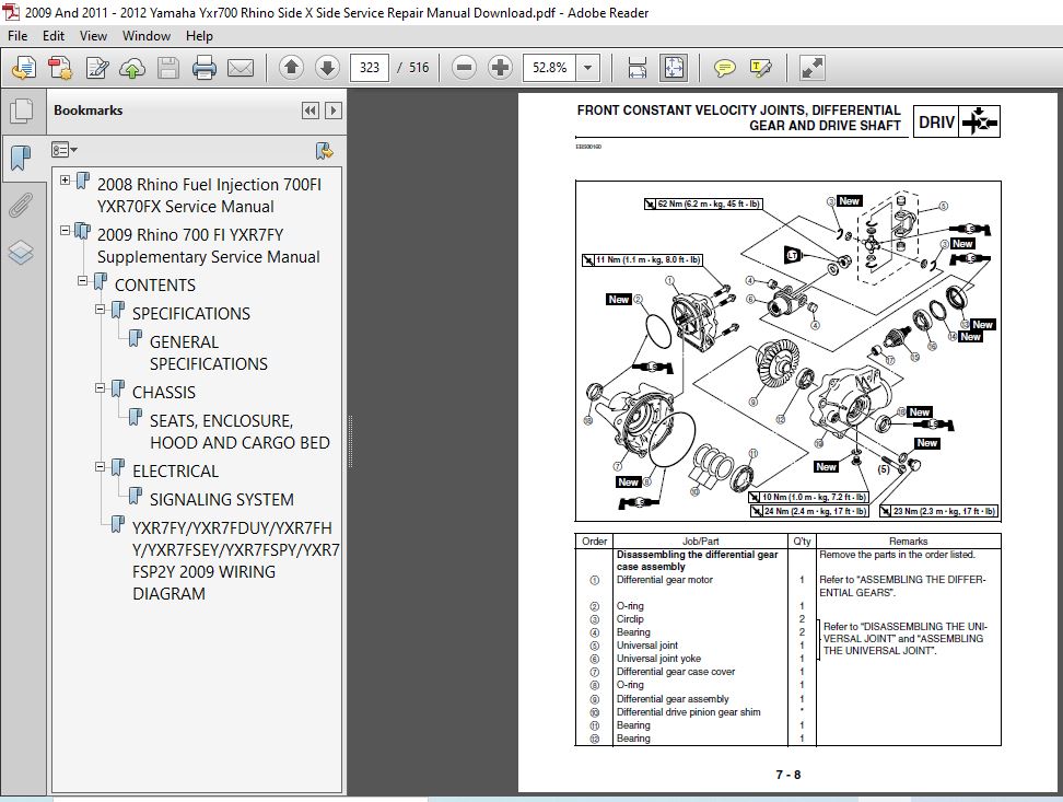
Front Constant Velocity Joints, Differential Gear And Drive Shaft 319
Disassembling The Front Constant Velocity Joints 325
Disassembling The Universal Joint 326
Removing The Differential Gear Assembly 326
Checking The Front Constant Velocity Joints 327
Checking The Differential Gears 327
Checking The Differential Gear Motor 328
Assembling The Front Constant Velocity Joints 328
Assembling The Differential Gears 330
Assembling The Universal Joint 332
Measuring The Differential Gear Lash 332
Adjusting The Differential Gear Lash 333
Checking The Differential Gear Operation 334
Rear Constant Velocity Joints, Final Drive Gear And Drive Shaft 335
Disassembling The Rear Constant Velocity Joints 343
Assembling The Rear Constant Velocity Joints 344
Disassembling The Final Gear Case 346
Removing The Final Drive Roller Bearings 347
Installing The Final Drive Roller Bearings 347
Positioning The Final Drive Pinion Gear And Ring Gear 348
Checking The Drive Shaft 353
Checking The Final Gear Case 353
Measuring And Adjusting The Final Gear Lash 353
Assembling The Final Gear Case 355
Chapter 8 Chassis 15
Chassis 358
Seats, Enclosure, Hood And Cargo Bed 358
Front Guard And Hood 358
Seats, Rear Console And Instrument Panels 359
Removing The Steering Wheel 361
Installing The Steering Wheel 361
Side Doors 362
Panels And Front Console 363
Removing The Side Panels 365
Install The Side Panels 365
Cargo Bed 366
Skid Plates 368
Installing The Rear Skid Plate 369
Enclosure And Seat Belts 370
Installing The Enclosure 371
Front And Rear Wheels 372
Front Wheels 372
Rear Wheels 374
Checking The Wheels 376
Checking The Wheel Hubs 376
Checking The Brake Discs 377
Installing The Wheel Hubs 377
Installing The Wheels 377
Front And Rear Brakes 378
Front Brake Pads 378
Rear Brake Pads 379
Replacing The Front And Rear Brake Pads 380
Brake Master Cylinder 382
Checking The Master Cylinder 384
Assembling The Brake Master Cylinder 384
Installing The Brake Master Cylinder 385
Front Brake Caliper 387
Rear Brake Calipers 389
Disassembling The Front And Rear Brake Calipers 391
Checking The Front And Rear Brake Calipers 391
Assembling The Front And Rear Brake Calipers 392
Installing The Front And Rear Brake Calipers 393
Parking Brake 395
Parking Brake Pads 395
Replacing The Parking Brake Pads 396
Parking Brake 397
Parking Brake Disc 400
Checking The Parking Brake 401
Checking The Parking Brake Disc 401
Assembling The Parking Brake 401
Pedal Assembly 404
Steering System 406
Steering Shaft And Steering Assembly 406
Disassembling The Steering Assembly 409
Checking The Steering Joint 409
Checking The Steering Assembly 409
Assembling The Steering Assembly 410
Installing The Steering System 411
Tie-rod And Steering Knuckle 412
Removing The Steering Knuckles 413
Checking The Tie-rods 413
Checking The Steering Knuckles 413
Front Arms And Front Shock Absorbers 417
Removing The Front Arms 419
Checking The Front Arms 419
Handling The Front Shock Absorbers And Gas Cylinders 421
Disposing Of A Front Shock Absorber And Gas Cylinder 422
Checking The Front Shock Absorbers 422
Installing The Front Arms And Front Shock Absorber 423
Rear Knuckle And Stabilizer 424
Checking The Rear Knuckles 425
Checking The Stabilizer 425
Rear Arms And Rear Shock Absorber 426
Checking The Rear Arms 428
Handling The Rear Shock Absorbers And Gas Cylinders 428
Disposing Of A Rear Shock Absorber And Gas Cylinder 429
Checking The Rear Shock Absorbers 429
Installing The Rear Arms And Rear Shock Absorber 430
Chapter 9 Electrical 17
Electrical 431
Electrical Components 431
Checking Switch Continuity 433
Checking The Switches 434
Checking The Bulbs And Bulb Sockets 436
Types Of Bulbs 436
Checking The Condition Of The Bulbs 437
Checking The Condition Of The Bulb Sockets 438
Ignition System 439
Circuit Diagram 439
Troubleshooting 440
Electric Starting System 444
Circuit Diagram 444
Starting Circuit Operation 445
Troubleshooting 446
Starter Motor 449
Checking The Starter Motor 451
Assembling The Starter Motor 453
Charging System 454
Circuit Diagram 454
Troubleshooting 455
Lighting System 457
Circuit Diagram 457
Troubleshooting 458
Checking The Lighting System 460
Signaling System 462
Circuit Diagram 462
Troubleshooting 464
Checking The Signaling System 466
Cooling System 475
Circuit Diagram 475
Troubleshooting 476
Fuel Pump System 480
Circuit Diagram 480
Troubleshooting 481
2WD/4WD Selecting System 483
Circuit Diagram 483
Troubleshooting 484
Chapter 10 Troubleshooting 18
Troubleshooting 488
Starting Failure/Hard Starting 488
Fuel System 488
Electrical System 488
Compression System 489
Poor Idle Speed Performance 489
Poor Idle Speed Performance 489
Poor Medium And High-Speed Performance 489
Poor Medium And High-Speed Performance 489
Faulty Drive Train 490
Faulty Gear Shifting 491
Hard Shifting 491
Shift Lever Does Not Move 491
Jumps Out Of Gear 491
Faulty Clutch Performance 491
Engine Operates But Vehicle Will Not Move 491
Clutch Slipping 491
Poor Starting Performance 491
Poor Speed Performance 492
Overheating 492
Overheating 492
Overcooling 492
Cooling System 492
Faulty Brake 492
Poor Braking Effect 492
Shock Absorber Malfunction 493
Malfunction 493
Unstable Handling 493
Unstable Handling 493
Lighting System 493
Headlight Does Not Come On 493
Bulb Burnt Out 493
YXR70FX 2008 Wiring Diagram 494
YXR70FX 2008 Wiring Diagram 497
2009 Rhino 700 FI YXR7FY Supplementary Service Manual 498
CONTENTS 0
SPECIFICATIONS 504
GENERAL SPECIFICATIONS 505
CHASSIS 504
SEATS, ENCLOSURE, HOOD AND CARGO BED 507
ELECTRICAL 504
SIGNALING SYSTEM 509
YXR7FY/YXR7FDUY/YXR7FHY/YXR7FSEY/YXR7FSPY/YXR7FSP2Y 2009 WIRING DIAGRAM 516
VIDEO PREVIEW OF THE MANUAL:

IMAGES PREVIEW OF THE MANUAL:

PLEASE NOTE:
- This is the same manual used by the DEALERSHIPS to SERVICE your vehicle.
- The manual can be all yours – Once payment is complete, you will be taken to the download page from where you can download the manual. All in 2-5 minutes time!!
- Need any other service / repair / parts manual, please feel free to contact us at heydownloadss @gmail.com . We may surprise you with a nice offer


