

1963 Cessna 172 & 175 Parts Catalog Manual – PDF DOWNLOAD
IMAGES PREVIEW OF THE MANUAL:

DESCRIPTION:
1963 Cessna 172 & 175 Parts Catalog Manual – PDF DOWNLOAD
INTRODUCTION.
This illustrated parts catalog has been prepared to aid
you in easily and quickly identüying parts of the Cessna
Model 172, 172 Skyhawk, 175 and 175 Skylark.
This catalog features an index system consisting of:
l. An alphabetical index located in the front of the
catalog.
2. A numerical index located in the back of the
catalog, which lists all parts and figures in
which they appear.
STANDARD PARTS.
Many parts having standard usage have been incorporated
lnto the Cessna Standard System. Parts in this
group are deslgnated with the part number prefix “S-”
and are described wlth the pbrase “Cessna Standard”
in the nomenclature.
For standard hardware items sucb as Tlnnerman nuts,
clamps, etc., “AN” and “NAS” numbers have been
used. The vendors number aleo appears in the descrlption
column to aid in identifying the correct part.
TABLE OF CONTENTS:
1963 Cessna 172 & 175 Parts Catalog Manual – PDF DOWNLOAD
Menu – 172/175 Parts Catalog 56-62……………………………………….. 0
Toolbar Help…………………………………………………………… 0
Links to Parts Figures………………………………………………….. 0
Cover…………………………………………………………………. 1
Introduction…………………………………………………………… 3
Alphabetical Index……………………………………………………… 15
A – B……………………………………………………………… 16
B (cont) – C……………………………………………………….. 17
C (cont) – F……………………………………………………….. 19
F (cont) – G……………………………………………………….. 20
G (cont) – I……………………………………………………….. 21
I (cont) – L……………………………………………………….. 22
L (cont) – P……………………………………………………….. 23
P (cont) – R……………………………………………………….. 24
R (cont) – S……………………………………………………….. 25
S (cont) – U……………………………………………………….. 27
V – W……………………………………………………………… 28
Parts Listing / Figures…………………………………………………. 29
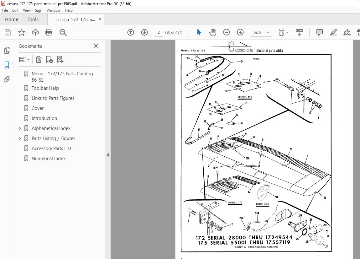
Fig 1. Wing Assembly Complete………………………………………… 30
Fig 2. Wing Structure Assembly……………………………………….. 34
Fig 3. Wing Structure Assembly……………………………………….. 36
Fig 4. Wing Leading Edge Assembly…………………………………….. 40
Fig 5. Wing Spars Assemblies…………………………………………. 42
Fig 6. Skins and Stringers Installation……………………………….. 44
Fig 7. Fuel Tank Installation………………………………………… 46
Fig 8. Fuel Tank Installation………………………………………… 50
Fig 9. Aileron Installation………………………………………….. 52
Fig 10. Flap Installation……………………………………………. 54
Fig 11. Wing Strut Assembly………………………………………….. 56
Fig 12. Fin and Dorsal Assembly………………………………………. 57
Fig 12A. Fin & Dorsal Installation……………………………………. 59
Fig 13. Stabilizer Installation………………………………………. 60
Fig 14. Rudder Assembly……………………………………………… 62
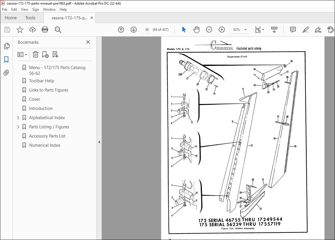
Fig 14A. Rudder Assembly…………………………………………….. 64
Fig 15. Elevator Installation………………………………………… 66
Fig 16. Fuselage Assembly……………………………………………. 68
Fig 16A. Fuselage Assembly…………………………………………… 70
Fig 17. Fuselage Front and Center Section Assembly……………………… 72
Fig 18. Fuselage Front Section Structure Assembly………………………. 76
Fig 19. Fuselage Front Section Structure Assembly………………………. 78
Fig 20. Front Doorpost Bulkhead Assembly………………………………. 82
Fig 21. Windshield Installation………………………………………. 85
Fig 22. Fuselage Tunnel Assembly……………………………………… 86
Fig 23. Battery Box Installation……………………………………… 87
Fig 23A. Battery Box Installation…………………………………….. 88
Fig 24. Firewall Assembly……………………………………………. 90
Fig 24A. Firewall Assembly…………………………………………… 91
Fig 25. Firewall Assembly……………………………………………. 92
Fig 26. Firewall Grommets Installation………………………………… 94
Fig 26A. Firewall Grommets Installation……………………………….. 96
Fig 27. Fuselage Aft Section Assembly…………………………………. 98
Fig 27A. Fuselage Aft Section Assembly…………………………………102
Fig 28. Fuselage Bulkhead Assembly Sta. 65.33…………………………..104
Fig 29. Landing Gear Bulkhead Assembly Sta. 44.00 to 65.33……………….106
Fig 30. Fuselage Top Skin Assembly Sta. 65.33 to 90.00…………………..108
Fig 31. Fuselage Tailcone Assembly Sta. 205.812 to 288.687……………….109
Fig 32. Nose Gear Installation………………………………………..110
Fig 32A. Nose Gear Installation……………………………………….114
Fig 33. Nose Gear Strut Assembly………………………………………118
Fig 33A. Nose Gear Strut Assembly……………………………………..122
Fig 34. Main Landing Gear Installation…………………………………124
Fig 34A. Main Landing Gear Installation………………………………..128
Fig 35. Front Seat Installation……………………………………….130
Fig 36. Front Seat Installation……………………………………….132
Fig 36A. Reclining Front Seat Installation……………………………..136
Fig 36B. Adjustable Front Seat………………………………………..140
Fig 37. Rear Seat Installation………………………………………..142
Fig 38. Rear Seat Installation………………………………………..144
Fig 38A. Auxiliary Seat Installation…………………………………..146
Fig 39. Upholstery Installation……………………………………….148
Fig 40. Upholstery Installation……………………………………….152
Fig 41. Floorboard and Baggage Compartment Upholstery Installation………..156
Fig 42. Left Cabin Door Installation…………………………………..160
Fig 42A. Left Cabin Door Installation………………………………….162
Fig 43. Right Cabin Door Installation………………………………….166
Fig 44. Cabin Door Latch Assembly……………………………………..168
Fig 45. Cabin Door Thumb Latch Assembly………………………………..169
Fig 45A. Baggage Door Installation…………………………………….170
Fig 46. Stationary Instrument Panel Equipment Installation……………….172
Fig 47. Stationary Instrument Panel Equipment Installation……………….176
Fig 48. Stationary Instrument Panel Assembly……………………………179
Fig 49. Glove Box and Door Installation………………………………..180
Fig 49A. Glove Box & Door Installation…………………………………182
Fig 50. Shock Mounted Instrument Panel Assembly…………………………184
Fig 51. Shock Mounted Instrument Panel Assembly…………………………188
Fig 51A. Instrument Panel Equipment Installation………………………..192
Fig 51B. Stationary Instrument Panel Equipment Installation………………196
Fig 52. Fuselage Equipment Installation………………………………..200
Fig 53. Portable Stretcher Installation Kit…………………………….203
Fig 53A. Portable Stretcher Installation……………………………….204
Fig 54. Propeller Installation………………………………………..205
Fig 54A. Propeller Installation……………………………………….206
Fig 54B. McCauley Constant Speed Propeller Installation………………….209
Fig 54C. McCauley Propeller Assembly…………………………………..210
Fig 55. Engine Cowl Assembly………………………………………….212
Fig 55A. Cowl Assembly……………………………………………….214
Fig 56. Engine Cowl Assembly………………………………………….216
Fig 56A. Engine Cowl Assembly…………………………………………218
Fig 57. Engine Installation…………………………………………..222
Fig 57A. Engine Installation………………………………………….224
Fig 58. Engine Installation…………………………………………..226
Fig 59. Engine Assembly………………………………………………230
Fig 59A. Engine Assembly……………………………………………..232
Fig 60. Engine Assembly………………………………………………236
Fig 60A. Engine Assembly……………………………………………..239
Fig 60B. Propeller Governor Assembly…………………………………..242
Fig 61. Engine Exhaust Stack Assembly………………………………….244
Fig 62. Engine Exhaust Stack Assembly………………………………….246
Fig 63. Engine Baffles Installation……………………………………248
Fig 64. Engine Baffles Installation……………………………………250
Fig 64A. Engine Baffles Installation…………………………………..252
Fig 64B. Engine Baffles Installation…………………………………..254
Fig 65. Winterization Equipment Installation……………………………258
Fig 66. Cabin Ventilating System………………………………………260
Fig 66A. Rear Seat Ventilation System………………………………….261
Fig 66B. Rear Seat Ventilating System………………………………….262
Fig 67. Cabin Heating and Defrosting System Installation…………………264
Fig 68. Cabin Heating and Defrosting System Installation…………………266
Fig 68A. Cabin Heating and Defrosting System Installation………………..268
Fig 69. Brake and Rudder Pedal Installation…………………………….272
Fig 70. Control Tee Installation………………………………………276
Fig 71. Rudder Control System Installation……………………………..280
Fig 71A. Rudder Control System Installation…………………………….282
Fig 72. Aileron Control System Installation…………………………….284
Fig 73. Flap Control System Installation……………………………….288
Fig 74. Elevator Control System Installation……………………………290
Fig 75. Elevator Trim Control System Installation……………………….292
Fig 76. Pitot System Installation……………………………………..294
Fig 77. Pitot System Installation……………………………………..296
Fig 78. Brake System Installation……………………………………..300
Fig 78A. Brake System Installation…………………………………….302
Fig 79. Fuel System Installation………………………………………306
Fig 79A. Auxiliary Fuel System………………………………………..310
Fig 80. Strainer and Drain Control Installation…………………………312
Fig 80A. Six Cylinder Priming System…………………………………..314
Fig 81. Oil System Installation……………………………………….318
Fig 82. Dual Venturi Gyro System………………………………………320
Fig 82A. Venturi & Gyros System……………………………………….324
Fig 82B. Vacuum System Installation……………………………………326
Fig 82C. Engine Driven Vacuum System Installation……………………….330
Fig 83. Vacuum System Installation…………………………………….334
Fig 83A. Autopilot Installation – Tactair T-1 & T-2……………………..336
Fig 83B. Autopilot Installation – Tactair T-3…………………………..340
Fig 83C. Tactair T-2 Autopilot Installation…………………………….342
Fig 84. Oxygen System Installation…………………………………….350
Fig 85. Manifold Pressure Gage and Carburetor Air Temp Gage Installations….352
Fig 86. Floatplane Fittings Installation……………………………….356
Fig 86A. Floatplane Fittings Installation………………………………358
Fig 87. Floatplane Fuselage Structure Details…………………………..360
Fig 87A. Floatplane Fuselage Structure Details………………………….362
Fig 88. Fuselage Electrical Equipment Installation………………………364
Fig 89. Fuselage Electrical Equipment Installation………………………368
Fig 90. 1 1/2 Minute Flares Installation……………………………….371
Fig 91. Cabin Lights and Speaker Installation…………………………..372
Fig 92. Landing Light Installation Kit…………………………………374
Fig 92A. Courtesy Light Installation…………………………………..375
Fig 93. Rotating Beacon Installation…………………………………..376
Fig 94 thru 97. Deleted………………………………………………378
Fig 98. Placards and Name Plates Installation…………………………..380
Fig 98A. Placards and Name Plates Installation………………………….382
Fig 99. Main Wheel and Brake Assembly………………………………….386
Fig 100. Nose Wheel Assembly………………………………………….390
Fig 100A. Nose Gear Wheel Assembly…………………………………….392
Fig 101. Shimmy Dampener Assembly……………………………………..394
Fig 102. Master Brake Cylinder………………………………………..396
Fig 103. Fuel Selector Valve Assembly………………………………….398
Fig 104. Rudder Centralizer Assembly…………………………………..399
Accessory Parts List…………………………………………………….400
Numerical Index…………………………………………………………403
PLEASE NOTE:
- This is the same manual used by the DEALERSHIPS to SERVICE your vehicle.
- The manual can be all yours – Once payment is complete, you will be taken to the download page from where you can download the manual. All in 2-5 minutes time!!
- Need any other service / repair / parts manual, please feel free to contact us at heydownloadss @gmail.com . We may surprise you with a nice offer
S.V


