

1962-1972 Cessna 182 Parts Catalog Manual – PDF DOWNLOAD
IMAGES PREVIEW OF THE MANUAL:
DESCRIPTION:
1962-1972 Cessna 182 Parts Catalog Manual – PDF DOWNLOAD
INTRODUCTION.
This illustrated parts catalog has been prepared to aid
you in easily and quickly identifying parts of the models
covered herein.
This catalog features an index system consisting of:
l. An alphabetical index located in the front of the
catalog.
2. A numerical index located in the back of the
catalog, which lists all parts and figures in
which they appear.
STANDARD PARTS.
Many parts having standard usage have been incorporated
into the Cessna Standard System. Parts in this
P-;ro11p are designated with the part number prefix “S”.
For standard hardware items such as Tinnerman nuts
clamps, etc., “AN” and “NAS” numbers have bee~
used.
USABLE ON CODES …. Serial listings in this catalog
are noted by a letter code located in the usable on code
column which is the extreme right hand column of the
narts list page. Usable rm codes are applicaLle only
‘.:o the figure on which they appear. The code letters
:md the serials to which they apply are Usted at the
, ~ nd of the figure.
1f no usable on code appears opposite a first column
Hsting of the figure, thf’ usage is applicable to all
1,10dels and serials covered by this catalog. If no
t·sable on code appears opposite any indented listing
t 1e usage is applicable to all models and serials cov:
ered by the figure on which it appears.
TABLE OF CONTENTS:
1962-1972 Cessna 182 Parts Catalog Manual – PDF DOWNLOAD
Menu – 182 Parts Catalog 62-73…………………………………………………………………………………………. 0
Toolbar Help…………………………………………………………………………………………………………. 0
Links to Parts Figures………………………………………………………………………………………………… 0
Inside Cover…………………………………………………………………………………………………………. 1
List of Effective Pages……………………………………………………………………………………………….. 2
Page 1…………………………………………………………………………………………………………… 2
Page 2…………………………………………………………………………………………………………… 3
Introduction…………………………………………………………………………………………………………. 5
Finish & Trim Plate…………………………………………………………………………………………………… 7
Paint Code Charts…………………………………………………………………………………………………….. 13
Upholstery & Interior Trim…………………………………………………………………………………………….. 21
Alphabetical Index……………………………………………………………………………………………………. 35
A……………………………………………………………………………………………………………….. 36
B……………………………………………………………………………………………………………….. 37
C……………………………………………………………………………………………………………….. 38
D-E……………………………………………………………………………………………………………… 40
E(cont)-F………………………………………………………………………………………………………… 41
F(cont) – G………………………………………………………………………………………………………. 42
G (cont) – I……………………………………………………………………………………………………… 43
I(cont)-K………………………………………………………………………………………………………… 44
K(cont)-M………………………………………………………………………………………………………… 45
M(cont)-O………………………………………………………………………………………………………… 46
O(cont)-R………………………………………………………………………………………………………… 47
R(cont)-S………………………………………………………………………………………………………… 48
S(cont)………………………………………………………………………………………………………….. 49
S(cont)-T………………………………………………………………………………………………………… 50
T(cont)-W………………………………………………………………………………………………………… 51
W(cont)………………………………………………………………………………………………………….. 52
Parts Listings/Figures………………………………………………………………………………………………… 53
Fig 1. Miscellaneous Bulk Items…………………………………………………………………………………….. 56
Fig 2. (Sheet 1) Placards, Nameplates & Exterior Markings……………………………………………………………… 58
Fig 2. (Sheet 2) Placards, Nameplates & Exterior Markings……………………………………………………………… 59
Fig 2. (Sheet 3) Placards, Nameplates and Exterior Markings……………………………………………………………. 60
Fig 2. (Sheet 4) Placards, Nameplates and Exterior Markings (182 Serial 18253599 thru 18259305)……………………………. 62
Fig 2. (Sheet 5) Placards, Nameplates and Exterior Markings (182 Serial 18253599 thru 18259305)……………………………. 64
Fig 2A. (Sheet 1) Placards, Nameplates & Exterior Markings (182 Serial 18259306 & on)…………………………………….. 66
Fig 2A. (Sheet 2) Placards, Nameplates & Exterior Markings (182 Serial 18259306 & on)…………………………………….. 68
Fig 2A. (Sheet 3) Placards, Nameplates & Exterior Markings (182 Serial 18259306 & on)…………………………………….. 70
Fig 2A. (Sheet 4) Placards, Nameplates & Exterior Markings (182 Serial 18259306 & on)…………………………………….. 72
Fig 3. Wing Assembly Complete………………………………………………………………………………………. 74
Fig 4. Wing Structure Assembly (182 Serial 18253599 thru 18260055)……………………………………………………… 80
Fig 4A. Wing Structure Assembly (182 Serial 18260056 thru 18260825)…………………………………………………….. 82
Fig 4B. Wing Structure Assembly (182 Serial 18260826 & on)…………………………………………………………….. 86
Fig 5. Wing Leading Edge Assembly (182 Serial 18253599 thru 18260055)…………………………………………………… 88
Fig 5A. Wing Leading Edge Assembly (182 Serial 18260056 thru 18260825)………………………………………………….. 92
Fig 5B. Wing Leading Edge Assembly (182 Serial 18260826 & on)………………………………………………………….. 94
Fig 6. Wing Spar Assemblies (182 Serial 18253599 thru 18260825)………………………………………………………… 96
Fig 6A. Wing Spar Assemblies (182 Serial 18260826 & on)………………………………………………………………..100
Fig 7. Skins and Stringers Installation (182 Serial 18253599 thru 18260825)………………………………………………102
Fig 7A. Skins & Stringers Installation (182 Serial 18260826 & on)……………………………………………………….106
Fig 8. Fuel Tank Installation……………………………………………………………………………………….108
Fig 8A. Fuel Tank Drain Valve Installation……………………………………………………………………………111
Fig 9. Aileron Installation…………………………………………………………………………………………112
Fig 10. Flap Installation…………………………………………………………………………………………..116
Fig 11. Wing Strut Installation……………………………………………………………………………………..118
Fig 12. Fin & Dorsal Installation (182 serial 18253599 thru 18261425)……………………………………………………120
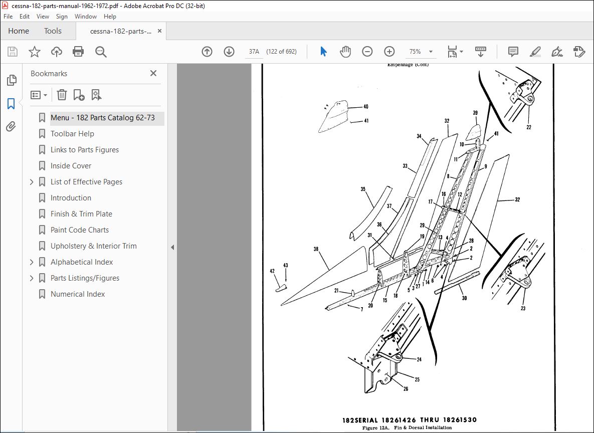
Fig 12A. Fin & Dorsal Installation (182 serial 18261426 thru 18261530)…………………………………………………..122
Fig 12B. Fin & Dorsal Installation (182 serial 18261531 & on)…………………………………………………………..124
Fig 13. Rudder Assembly…………………………………………………………………………………………….126
Fig 14. Stabilizer Installation (182 serial 18253599 thru 18255844)……………………………………………………..128
Fig 14A. Stabilizer Installation (182 Serial 18255845 & on)…………………………………………………………….130
Fig 15. Elevator Installation (182 serial 18253599 thru 18255844)……………………………………………………….134
Fig 15A. Elevator Installation (182 Serial 18255845 & on)………………………………………………………………138
Fig 16. Fuselage Assembly…………………………………………………………………………………………..140
Fig 17. Fuselage Front Section Assembly (182 Serial 18253599 thru 18260055)………………………………………………142
Fig 17A. Fuselage Front Section Assembly (182 serial 18260056 & on)……………………………………………………..148
Fig 18. Front Doorpost Bulkhead Assembly……………………………………………………………………………..152
Fig 19. Console Structure Assembly…………………………………………………………………………………..156
Fig 20. Front Section Tunnel Components………………………………………………………………………………158
Fig 21. Firewall Assembly (182 serial 18253599 thru 18258505)…………………………………………………………..160
Fig 21A. Firewall Assembly (182 serial 18258506 thru 18261425)………………………………………………………….162
Fig 21B. Firewall Assembly (182 serial 18261426 & on)………………………………………………………………….164
Fig 22. Firewall Grommets Installation……………………………………………………………………………….166
Fig 23. Center Cabin Section Assembly (182 serial 18253599 thru 18255058)………………………………………………..168
Fig 23A. Center Cabin Section Assembly (182 serial 18255059 & on)……………………………………………………….172
Fig 24. Rear Doorpost Bulkhead Assembly………………………………………………………………………………176
Fig 25. Lower Cabin Section Assembly (182 serial 18253599 & on)…………………………………………………………178
Fig 26. Landing Gear Bulkhead Assembly (182 serial 18253599 thru 18260825)……………………………………………….182
Fig 26A. Landing Gear Bulkhead Assembly (182 serial 18260826 & on)………………………………………………………184
Fig 27. Windshield Installation (182 serial 18253599 thru 18255844)……………………………………………………..186
Fig 27A. Windshield Installation (182 serial 18255845 & on)…………………………………………………………….187
Fig 28. Rear Window Installation (182 serial 18253599 thru 18255058)…………………………………………………….189
Fig 28A. Aft Cabin Windows Installation (182 serials 18255059 & on)……………………………………………………..190
Fig 29. Tailcone Assembly Sta. 110.00 to 230.187 (182 serial 18253599 thru 18255058)………………………………………192
Fig 29A. Fuselage Tailcone Assembly (A182 serial A182-0001 thru A182-0136, 182 serial 18255059 thru 18260445)………………..196
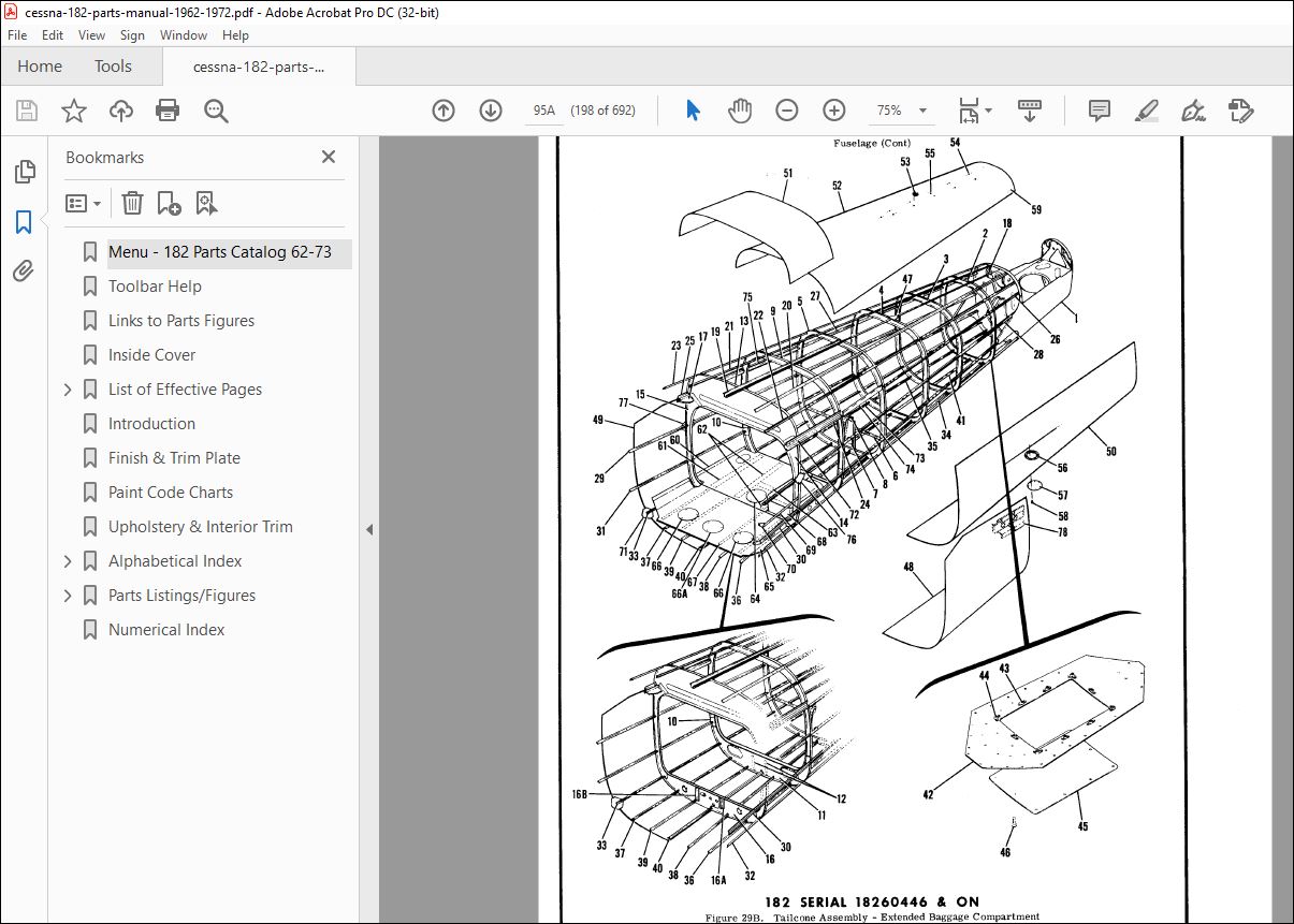
Fig 29B. Tailcone Assembly – Extended Baggage Compartment (182 serial 18260446 & on)………………………………………198
Fig 30. Battery Box Installation…………………………………………………………………………………….202
Fig 31. Aft Tailcone Assembly Sta. 209.00 to 230.187 (182 serial 18253599 thru 18261530)…………………………………..204
Fig 31A. Aft Tailcone Assembly Sta. 209.00 to 230.187 (182 serial 18261531 & on)………………………………………….206
Fig 32. Stinger Installation………………………………………………………………………………………..208
Fig 33. Nose Gear Installation………………………………………………………………………………………210
Fig 33A. Heavy Duty Nose Gear Installation (182 serial 18253599 thru 18260825)……………………………………………212
Fig 34. Nose Gear Steering System Installation………………………………………………………………………..214
Fig 35. Nose Gear Shock Strut Assembly……………………………………………………………………………….216
Fig 35A. Nose Gear Shock Strut Assembly – Heavy Duty (182 serial 18253599 thru 18260825)…………………………………..220
Fig 36. Goodyear Nose Wheel Assembly (182 serial 18253599 thru 18255844)…………………………………………………222
Fig 36A. Cleveland Nose Wheel Assembly (182 serial 18255845 & on)……………………………………………………….223
Fig 36B. Nose Gear Wheel Assembly – Alternate…………………………………………………………………………224
Fig 37. Cleveland Nose Wheel Assembly (182 serial 18253599 thru 18254423)………………………………………………..225
Fig 37A. Nose Wheel Assembly – Heavy Duty (Cleveland) – (182 serial 18254700 thru 18255058)………………………………..226
Fig 37B. Nose Wheel Assembly – Heavy Duty (Cleveland) – (182 serial 18253599 thru 18254699 & 18255059 thru 18260825)………….227
Fig 38. Shimmy Dampener Assembly (182 serial 18253599 thru 18255194)…………………………………………………….228
Fig 38A. Shimmy Dampener Assembly (182 serial 18255195 thru 18257625)……………………………………………………229
Fig 38B. Shimmy Dampener Assembly (182 serial 18257626 & on)……………………………………………………………230
Fig 39. Main Landing Gear Installation (A182 serial A182-0001 & on, 182 serial 18253599 thru 18260445)………………………232
Fig 39A. Main Landing Gear Installation (182 serial 18260446 thru 18260825)………………………………………………236
Fig 39B. Main Landing Gear Installation (182 serial 18260826 & on)………………………………………………………240
Fig 40. Main Wheel & Brake Assembly (182 serial 18253599 thru 18255844)………………………………………………….242
Fig 40A. Main Wheel & Brake Assembly (182 serial 18255845 & on)…………………………………………………………244
Fig 41. Left Cabin Door Assembly (182 serial 18253599 thru 18261425)…………………………………………………….248
Fig 41A. Left Cabin Door Assembly (182 serial 18261426 & on)……………………………………………………………252
Fig 42. Right Cabin Door Assembly (182 serial 18253599 thru 18261425)……………………………………………………256
Fig 42A. Right Cabin Door Assembly (182 serial 18261426 & on)…………………………………………………………..258
Fig 43. Cabin Door Latch Assembly (182 serial 18253599 thru 18256684)……………………………………………………260
Fig 43A. Cabin Door Latch Assembly (182 serial 18256685 & on)…………………………………………………………..262
Fig 44. Baggage Door Installation……………………………………………………………………………………264
Fig 45. Cabin Top & Firewall Upholstery Installation (182 serial 18253599 thru 18254423)…………………………………..266
Fig 45A. Cabin Top & Firewall Upholstery Installation(A182 serial A182-0001 thru A182-0136, 182 serial 18254424 thru 18260445….270
Fig 45B. Cabin Top & Firewall Upholstery Installation (182 serial 18260446 & on)………………………………………….272
Fig 46. Cabin Door Upholstery Installation……………………………………………………………………………276
Fig 47. Cabin Side & Floorboard Upholstery Installation (182 serial 18253599 thru 18254423)………………………………..278
Fig 47A. Cabin Side & Floorboard Upholstery Installation (182 serial 18254424 thru 18258505)……………………………….280
Fig 47B. Upholstery Cabin Side & Floorboard Installation(A182 serial A182-0097 thru A182-0136, 182 serial 18258506-18260445)…..284
Fig 47C. Upholstery Cabin Side & Floorboard Installation (182 serial 18260446 thru 18261425)……………………………….288
Fig 47D. Upholstery Cabin Side & Floorboard Installation (182 serial 18261426 & on)……………………………………….290
Fig 47E. Fuselage Soundproofing Installation(A182 serial A182-0001 thru A182-0116, 182 serial 18253599 thru 18260445)…………294
Fig 47F. Fuselage Soundproofing Installation (182 serial 18260446 & on)………………………………………………….295
Fig 48. Front Seat Installation (182 serial 18253599 thru 18254423)……………………………………………………..296
Fig 49. Pilot & Co-pilot Seat Installation (182 serial 18254424 thru 18258505)……………………………………………298
Fig 49A. Pilot & Co-Pilot Seat Installation (182 serial 18258506 thru 18260825)…………………………………………..302
Fig 49B. Pilot &Co-Pilot Seat Installation (182 serial 18260826 thru 18261425)……………………………………………304
Fig 49C. Pilot & Co-Pilot Seat Installation – Standard (182 serial 18261426 & on)…………………………………………308
Fig 50. Adjustable Front Seat Installation (182 serial 18253599 thru 18254423)……………………………………………310
Fig 51. Adjustable Seat Bottom Mechanism Installation (182 serial 18253599 thru 18254423)………………………………….312
Fig 51A. Vertically Adjustable Seat Installation (182 serial 18254424 thru 18260055)………………………………………316
Fig 51B. Pilot & Co-Pilot Power Adjustable Seat Installation (182 serial 18255238 thru 18257625)……………………………320
Fig 51C. Power Seat Bottom Assembly – Pilot & Co-Pilot (182 serial 18255238 thru 18257625)…………………………………324
Fig 51D. Infinite Adjust Front Seat Installation (182 serial 18260056 thru 18260825)………………………………………326
Fig 51E. Infinite Adjust Front Seat Installation (182 serial 18260826 thru 18261425)………………………………………330
Fig 51F. Infinite Adjust Front Seat Installation (182 serial 18261426 & on)………………………………………………334
Fig 52. Rear Seat Installation (182 serial 18253599 thru 18254423)………………………………………………………338
Fig 52A. Rear Seat Installation (182 serial 18254424 thru 18260825)……………………………………………………..340
Fig 52B. Rear Seat Installation (182 serial 18260826 & on)……………………………………………………………..344
Fig 52C. Auxiliary Seat Installation (182 serial 18254424 thru 18260055)…………………………………………………348
Fig 52D. Auxiliary Seat Installation (182 serial 18260056 & on)…………………………………………………………350
Fig 53. Instrument Panel Equipment Installation (182 serial 18253599 thru 18255844)……………………………………….352
Fig 53A. Instrument Panel Equipment Installation (182 serial 18255845 thru 18257625)………………………………………356
Fig 53B. Post Lighted Instrument Panel Installation (182 serial 18255845 thru 18257625)……………………………………360
Fig 53C. Instrument Panel Equipment Installation (182 serial 18257626 thru 18258505)………………………………………362
Fig 53D. Post Lighted Instrument Panel Installation (182 serial 18257626 thru 18258505)……………………………………366
Fig 53E. Instrument Panel Equipment Installation (182 serial 18258506 thru 18259305)………………………………………368
Fig 53F. Post Lighted Instrument Panel Installation (182 serial 18258506 thru 18259305)……………………………………374
Fig 53G. Instrument Panel Equipment Installation (182 serial 18259306 thru 18260055)………………………………………376
Fig 53H. Post Lighted Instrument Panel Installation (182 serial 18259306 thru 18260055)……………………………………382
Fig 53J. Instrument Panel Equipment Installation(A182 serial A182-0117 & on, 182 serial 18260056 thru 18260445)………………384
Fig 53K. Post Lighted Instrument Panel Installation(A182 serial A182-0117 & on, 182 serial 18260056 thru 18260445)……………390
Fig 53L. Instrument Panel Equipment Installation (182 serial 18260446 thru 18260825)………………………………………392
Fig 53M. Post Lighted Instrument Panel Installation (182 serial 18260446 thru 18260825)……………………………………398
Fig 53N. Instrument Panel Equipment Installation (182 serial 18260826 thru 18261425)………………………………………400
Fig 53P. Post Lighted Instrument Panel Installation (182 serial 18260826 thru 18261425)……………………………………406
Fig 53Q. Instrument Panel Equipment Installation(182 serial 18261426 & on)……………………………………………….408
Fig 53R. Post Lighted Instrument Panel Installation (182 serial 18261426 & on)……………………………………………414
Fig 54. Switch Panel Installation (182 serial 18253599 thru 18255844)……………………………………………………416
Fig 55. Map Compartment Installation (182 serial 18253599 thru 18255844)…………………………………………………418
Fig 55A. Map Compartment Installation (182 serial 18255845 & on)………………………………………………………..420
Fig 56. Fuselage Equipment Installation………………………………………………………………………………422
Fig 57. Portable Stretcher Installation………………………………………………………………………………427
Fig 57A. Rear View Mirror & Compass Installation (182 serial 18255845 thru 18261425)………………………………………428
Fig 57B. Rear View Mirror & Compass Installation (182 serial 18261426 & on)………………………………………………430
Fig 58. Propeller Installation (182 serial 18253599 thru 18255844)………………………………………………………432
Fig 58A. Propeller Installation (182 serial 18255845 & on)……………………………………………………………..434
Fig 59. McCauley Propeller Assembly (182 serial 18253599 thru 18254275)………………………………………………….436
Fig 59A. McCauley Propeller Installation (182 serial 18254276 thru 18259421)……………………………………………..438
Fig 59B. McCauley Propeller Assembly (182 serial 18259422 & on)…………………………………………………………442
Fig 60. Hartzell Propeller Assembly (182 serial 18253599 thru 18255058)………………………………………………….444
Fig 61. Engine Cowl Assembly (182 serial 18253599 thru 18255844)………………………………………………………..446
Fig 61A. Engine Cowl Assembly (182 serial 18255845 thru 18260055)……………………………………………………….450
Fig 61B. Engine Cowl Assembly (182 serial 18260056 thru 18261425)……………………………………………………….454
Fig 61C. Engine Cowl Assembly(182 serial 18261426 & on)………………………………………………………………..458
Fig 62. Engine Installation…………………………………………………………………………………………462
Fig 63. Engine Assembly…………………………………………………………………………………………….464
Fig 64. Propeller Governor Assembly (182 serial 18253599 thru 18254760)………………………………………………….472
Fig 64A. Propeller Governor Assembly (182 serial 18254761 thru 18255058)…………………………………………………474
Fig 64B. Propeller Governor Assembly (182 serial 18255059 & on)…………………………………………………………476
Fig 64C. Governor Assembly (182 serial 18255059 & on)………………………………………………………………….478
Fig 65. Exhaust Stack Assembly (182 serial 18253599 thru 18255058)………………………………………………………480
Fig 65A. Engine Exhaust Assembly (182 serial 18255059 & on)…………………………………………………………….482
Fig 66. Engine Baffles Installation………………………………………………………………………………….484
Fig 67. Cowl Flaps Control System Installation………………………………………………………………………..488
Fig 68. Winterization Equipment Installation (182 serial 18253599 thru 18255844)………………………………………….490
Fig 68A. Winterization Equipment Installation(182 serial 18255845 thru 18260055)………………………………………….491
Fig 68B. Winterization Equipment Installation (182 serial 18260056 & on)…………………………………………………492
Fig 69. Cabin Ventilation System (182 serial 18253599 thru 18257625)…………………………………………………….494
Fig 69A. Cabin Ventilation System (182 serial 18257626 & on)……………………………………………………………498
Fig 70. Cabin Heating & Defrosting System…………………………………………………………………………….500
Fig 71. Brake System Installation (182 serial 18253599 thru 18258399)……………………………………………………504
Fig 71A. Brake System Installation (182 serial 18258400 & on)…………………………………………………………..508
Fig 72. Brake & Rudder Pedals Installation……………………………………………………………………………510
Fig 73. Master Brake Cylinder Assembly……………………………………………………………………………….512
Fig 74. Control Column Installation (182 serial 18253599 thru 18258505)………………………………………………….514
Fig 74A. Control Column Installation (182 serial 18258506 & on)…………………………………………………………518
Fig 74B. Control Wheel & Switches Installation (182 serial 18258506 thru 18260825)………………………………………..522
Fig 74C. Control Wheel & Switches Installation (182 serial 18260826 & on)………………………………………………..524
Fig 75. Console Installation………………………………………………………………………………………..528
Fig 76. Aileron Control System Installation (182 serial 18253599 thru 18258505)…………………………………………..530
Fig 76A. Aileron Controls Installation (182 serial 18258506 & on)……………………………………………………….534
Fig 76B. Wing Leveler Installation (182 serial 18258506 & on)…………………………………………………………..536
Fig 77. Elevator Control System……………………………………………………………………………………..540
Fig 78. Elevator Trim Control System…………………………………………………………………………………544
Fig 79. Electric Flap System Installation…………………………………………………………………………….546
Fig 79A. Flap Actuator Transmission and Motor Assembly (182 serial 18255845 thru 18257066)…………………………………552
Fig 79B. Flap Control Detail Installation (A182 serial A182-0097 & on, 182 serial 18258506 thru 18260445)……………………554
Fig 79C. Flap Control Detail Installation (182 serial 18260446 & on)…………………………………………………….556
Fig 80. Rudder Control System Installation……………………………………………………………………………560
Fig 81. Pitot System Installation……………………………………………………………………………………562
Fig 82. Fuel System Installation (182 serial 18253599 thru 18255785)…………………………………………………….566
Fig 82A. Fuel System Installation (182 serial 18255786 & on)……………………………………………………………570
Fig 83. Fuel Strainer Assembly (182 serial 18253599 thru 18256039)………………………………………………………572
Fig 84. Fuel Strainer Drain Control Installation (182 serial 18253599 thru 18256039)………………………………………573
Fig 84A. Fuel Strainer & Drain Control Installation (182 serial 18256040 & on)……………………………………………574
Fig 85. Fuel Primer System Installation………………………………………………………………………………576
Fig 86. Oil System Installation……………………………………………………………………………………..578
Fig 86A. Directional & Horizontal Gyro Usage………………………………………………………………………….581
Fig 87. Vacuum System Installation (182 serial 18253599 thru 18255844)…………………………………………………..582
Fig 88. Vacuum System Installation (182 serial 18255845 thru 18257625)…………………………………………………..586
Fig 88A. Vacuum System Installation (182 serial 18257626 thru 18258505)………………………………………………….588
Fig 88B. Vacuum System Installation (A182 serial A182-0097 & on, 182 serial 18258506 thru 18260445)…………………………592
Fig 88C. Vacuum System Installation (182 serial 18260446 & on)………………………………………………………….594
Fig 89. Oxygen System Installation (182 serial 18253599 thru 18255844)…………………………………………………..598
Fig 89A. Oxygen System Installation (182 serial 18255845 thru 18260055)………………………………………………….600
Fig 89B. Oxygen System Installation (182 serial 18260056 thru 18260445)………………………………………………….604
Fig 89C. Oxygen System Installation (182 serial 18260446 & on)………………………………………………………….608
Fig 90. Electrical Equipment Installation…………………………………………………………………………….612
Fig 90A. Instrument Panel Lights Installation (182 serial 18260056 & on)…………………………………………………618
Fig 91. Instrument Panel Light Installation (182 serial 18253599 thru 18260055)…………………………………………..620
Fig 91A. Instrument Panel Light & Console Installation (182 serial 18260056 & on)…………………………………………622
Fig 92. Rotating Beacon Installation (182 serial 18253599 thru 18257625)…………………………………………………624
Fig 92A. Flashing Beacon Light Installation (182 serial 18257626 & on)…………………………………………………..626
Fig 93. Courtesy Light Installation………………………………………………………………………………….628
Fig 94. Map Light Installation (182 serial 18255059 thru 18260055)………………………………………………………630
Fig 95. Shock Mounted Alternator Installation (182 serial 18257446 & on)…………………………………………………632
Numerical Index……………………………………………………………………………………………………….633
PLEASE NOTE:
- This is the SAME exact manual used by your dealers to fix your vehicle.
- The same can be yours in the next 2-3 mins as you will be directed to the download page immediately after paying for the manual.
- Any queries / doubts regarding your purchase, please feel free to contact [email protected]
S.V


